
Exterminate Mitsubishi WD-65735 white dots with a new 4719-001997 DLP Chip
 Get rid of those white dots on your Mitsubishi WD-65735 with a new 4719-001997 DLP Chip
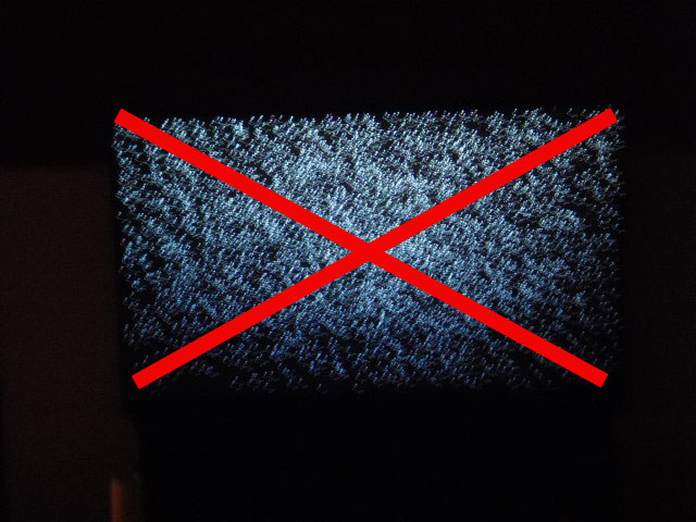
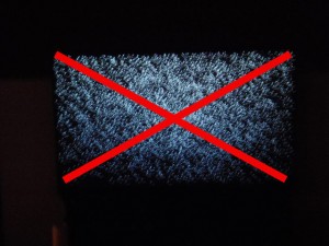
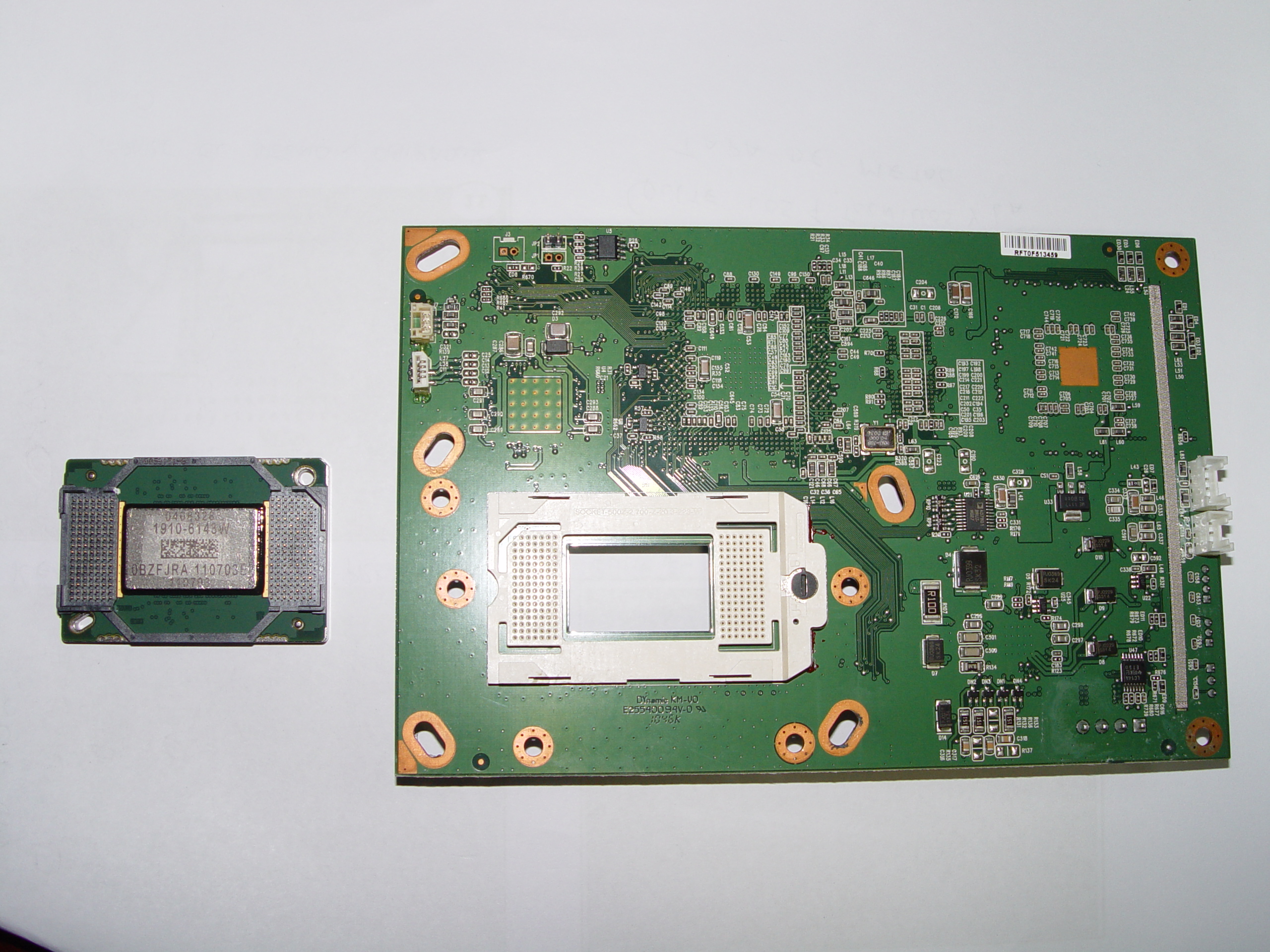
Those star-shaped dots that are taking over your screen are caused by a worn out 4719-001997 DLP Chip. Known as Mitsubishi white death syndrome, this problem can be solved by installing a new Mitsubishi/Toshiba 4719-001997 DLP Chip 1910-6143W.
Note: These instructions can also be used for the following Mitsubishi models:
WD-57733, WD-57734, WD-57833, WD-60638, WD-60733,WD-60735, WD-60737,WD-60738, WD-60833, WD-60837, WD-60C8,WD-60C9, WD-65638,WD-65731, WD-65733,WD-65734, WD-65735, WD-65736, WD-65737, WD-65738,WD-65833,WD-65835,WD-65837, WD-65838,WD-65C8,WD-65C9, WD-73638, WD-73640, WD-73642, WD-73733, WD-73734, WD-73735, WD-73736,WD-73737, WD-73738, WD-73833, WD-73835,WD-73837,WD-73838, WD-73840, WD-73C11, WD-73C8, WD-73C9, WD-75837, WD-82737, WD-82738, WD-82838, WD-Y657 WD-C657,WD-Y577.
Find this new Mitsubishi/Toshiba 4719-001997 DLP Chip 1910-6143W on Amazon and then follow our step-by-step visual guide.
Equipment needed
- Electric Philips screwdriver
- needle nose pliers or a 5mm nut driver
- antistatic gloves OR plastic gloves used with an antistatic wrist band
- soft cloth or brush
How to replace the 4719-001997 DLP Chip
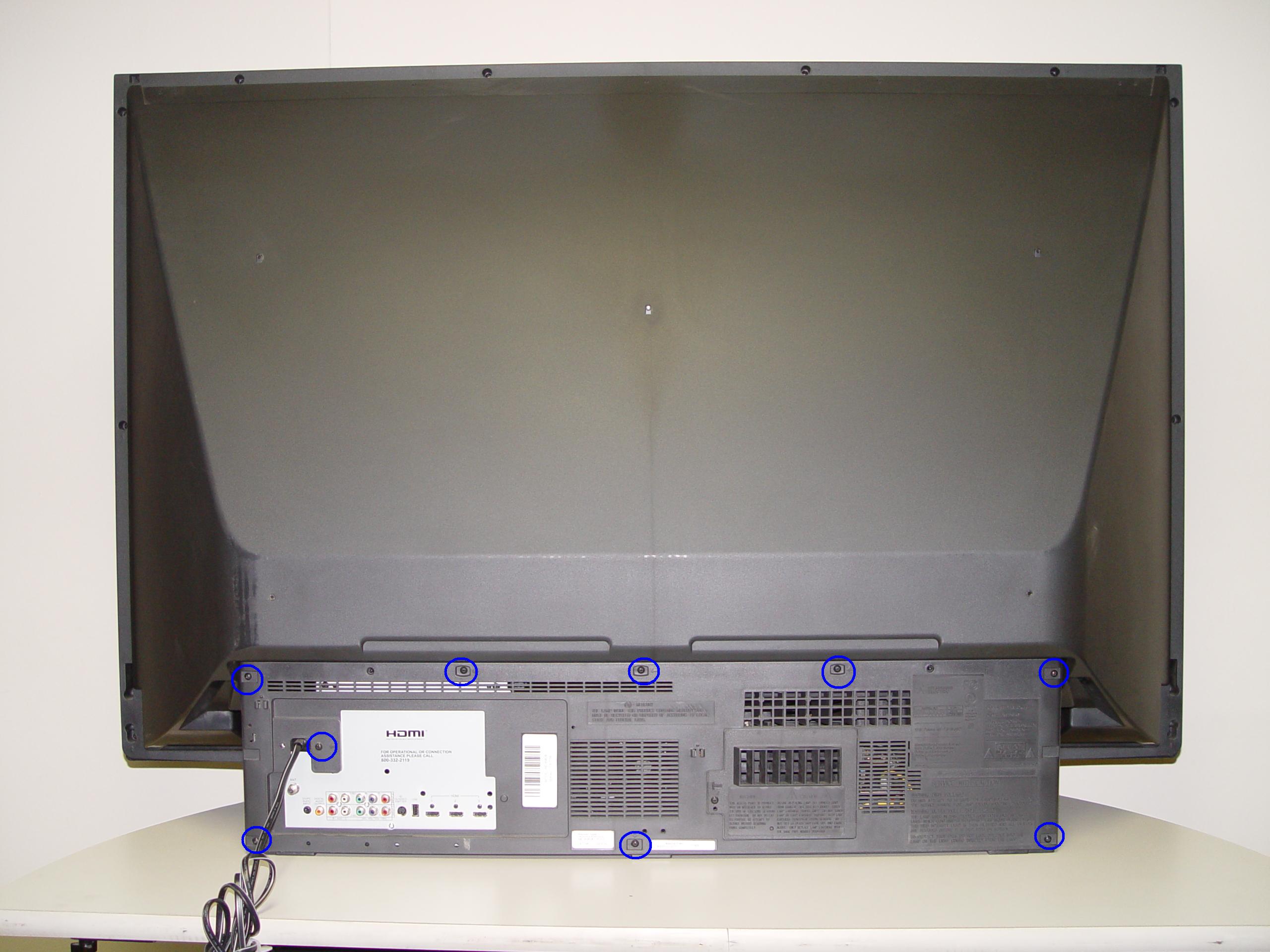
Step 1
Step 1: Put on the plastic gloves. Loosen all the screws found on the back panel.
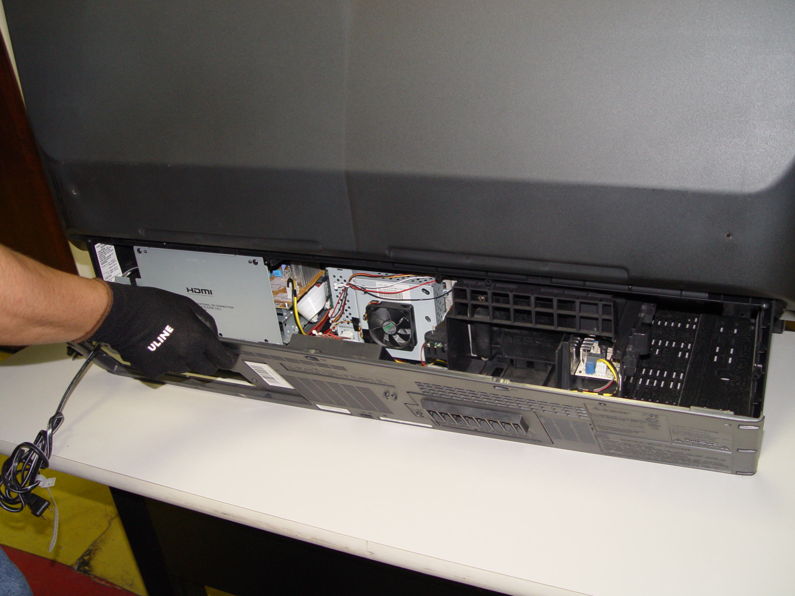
Step 2
Step 2: Put the screws to the side. Gently remove the back panel.
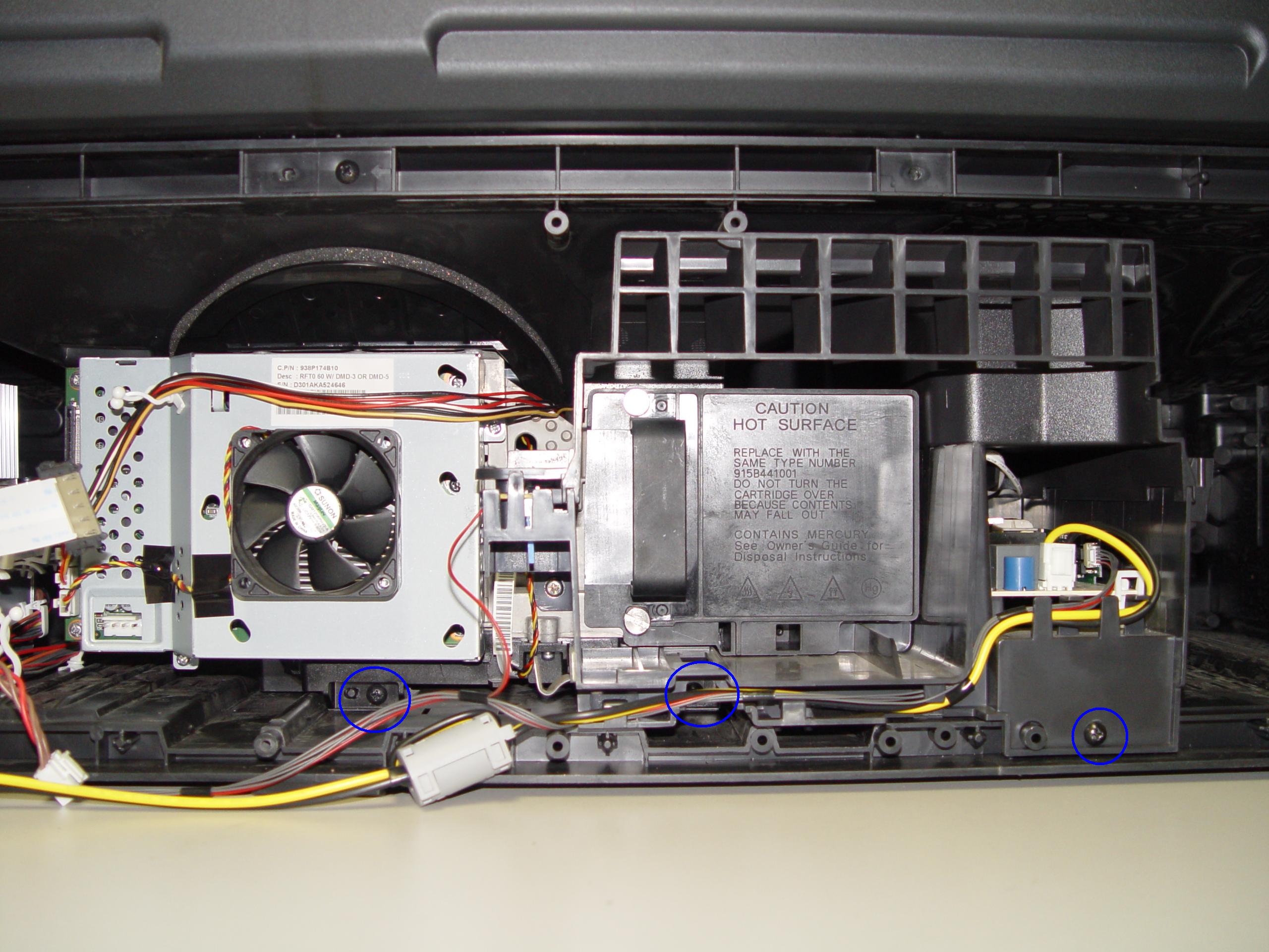
Step 3
Step 3: Remove the 3 screws holding the lamp engine in place.
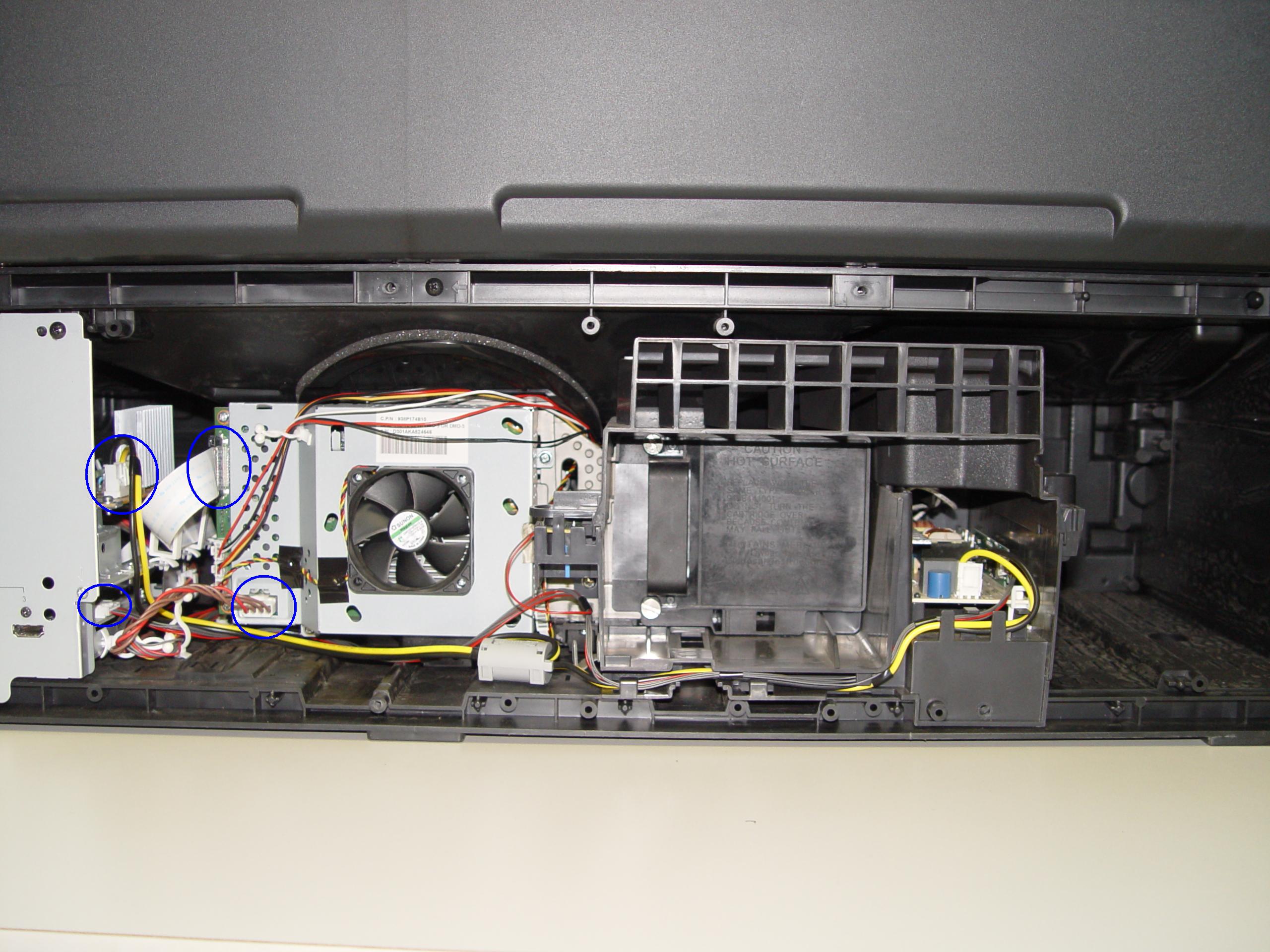
Step 4
Step 4: Disconnect all the connectors. Important: don’t yank any cables.
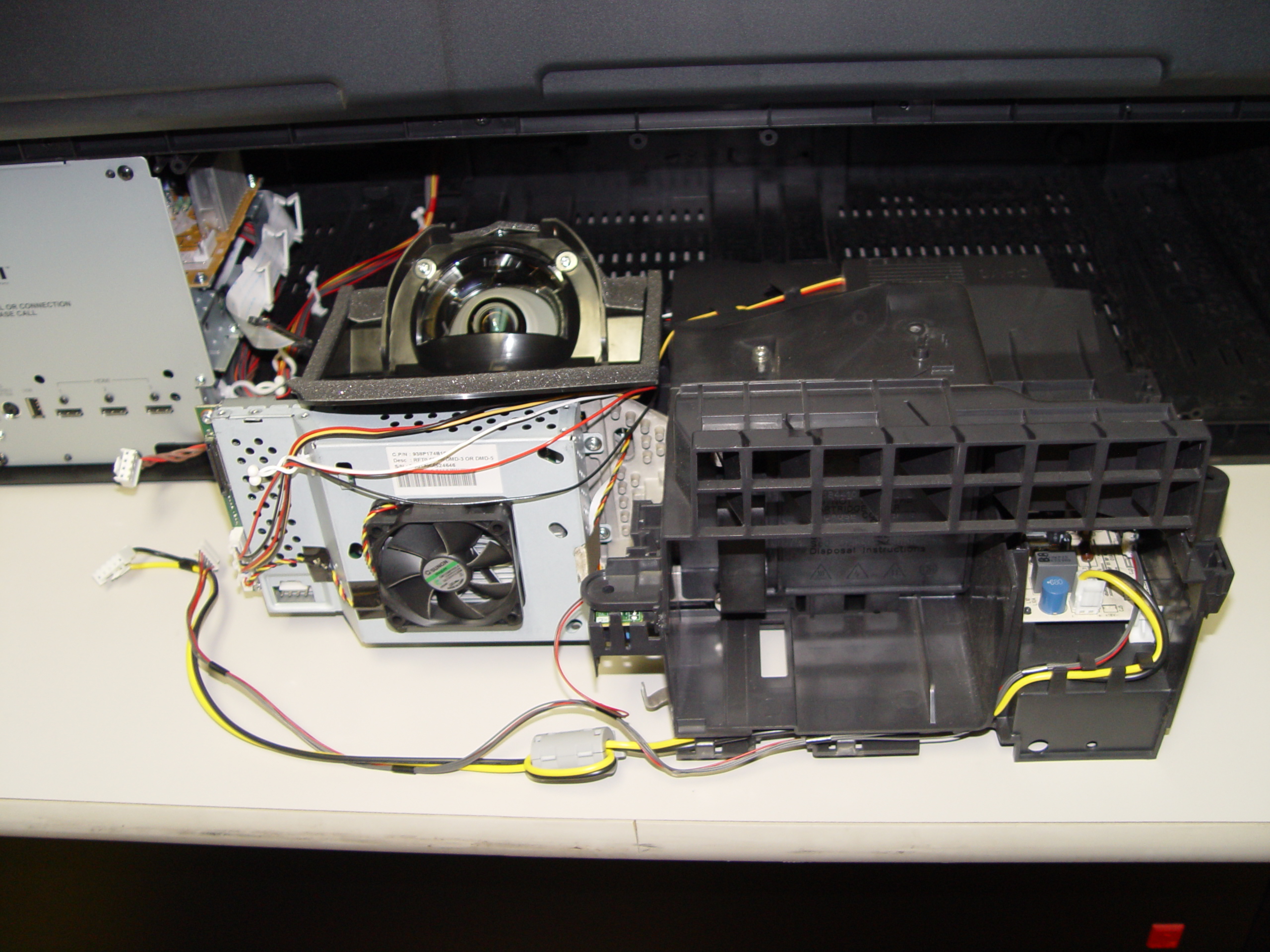
Step 5
Step 5: Carefully slide the light engine from the cabinet.
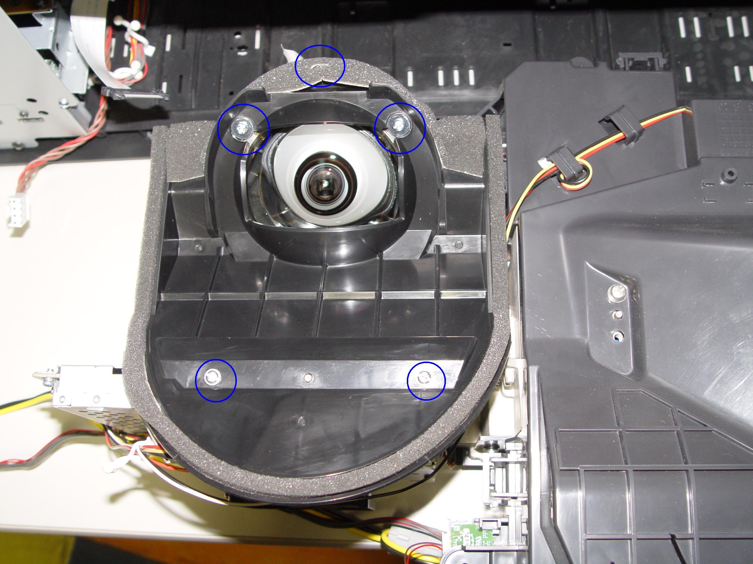
Step 6
Step 6: Remove the 3 screws holding the color wheel protective cover in it place. Avoid touching any of the optical components as this can affect the quality of your picture.
Step 7
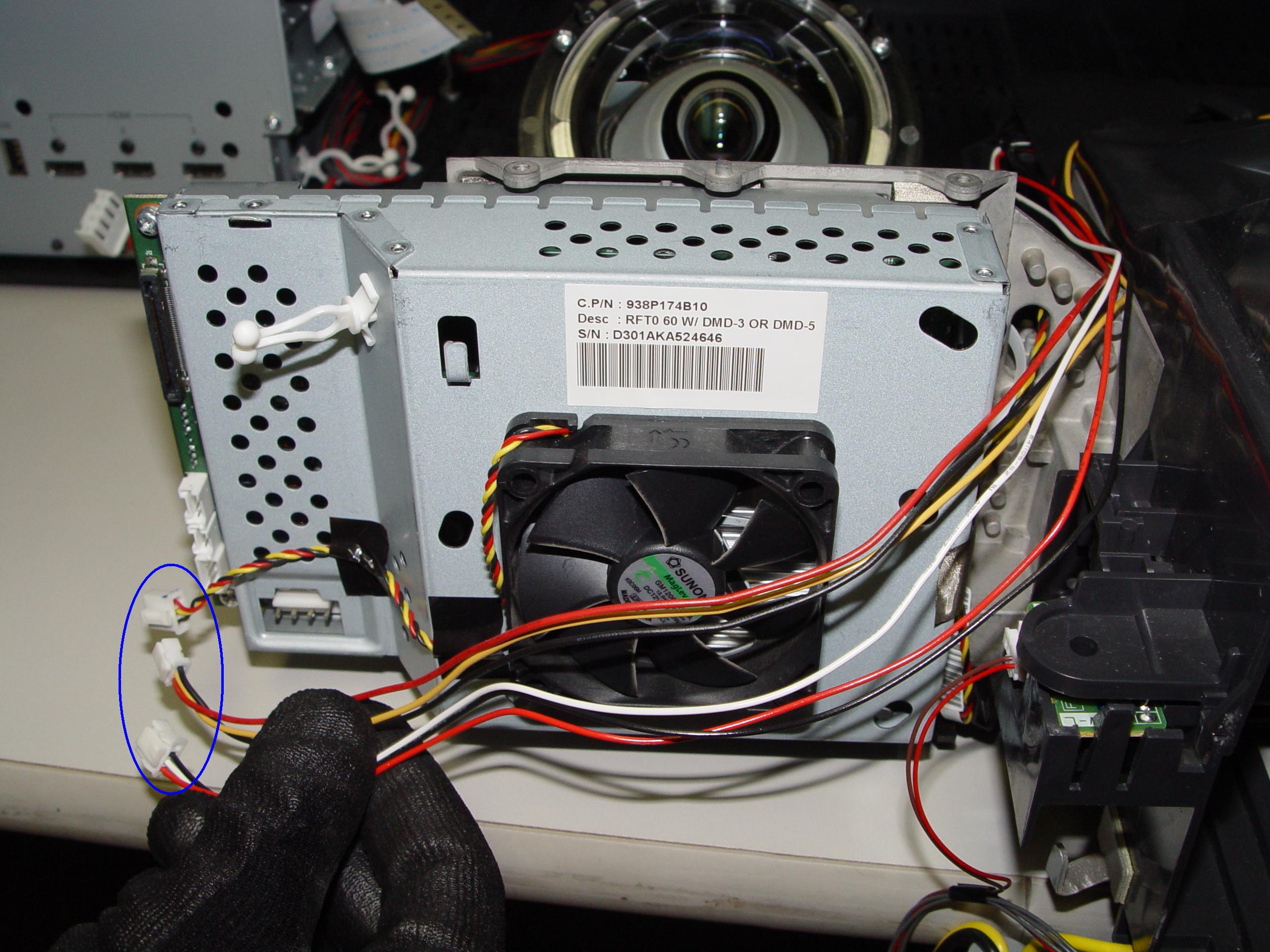
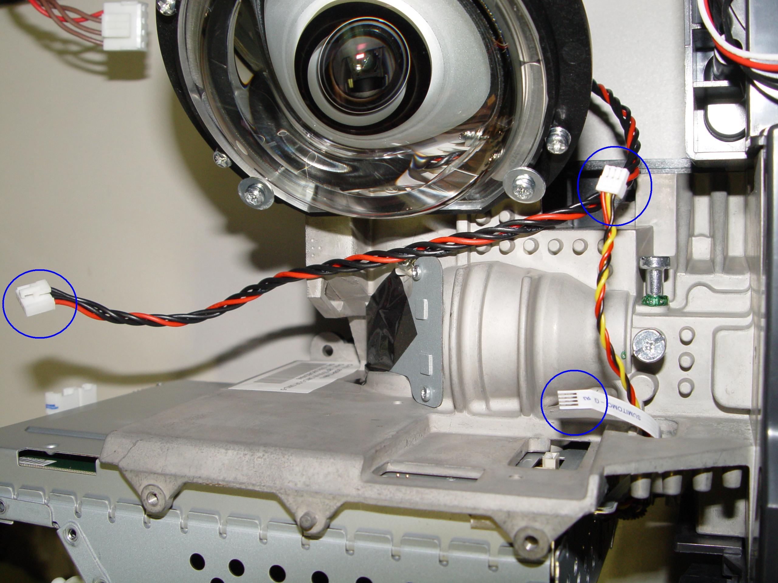
Step 7: Carefully disconnect the cable between the terminal board and lamp.
Step 8
Step 8: Disconnect the cables connecting the color wheel.
Step 9
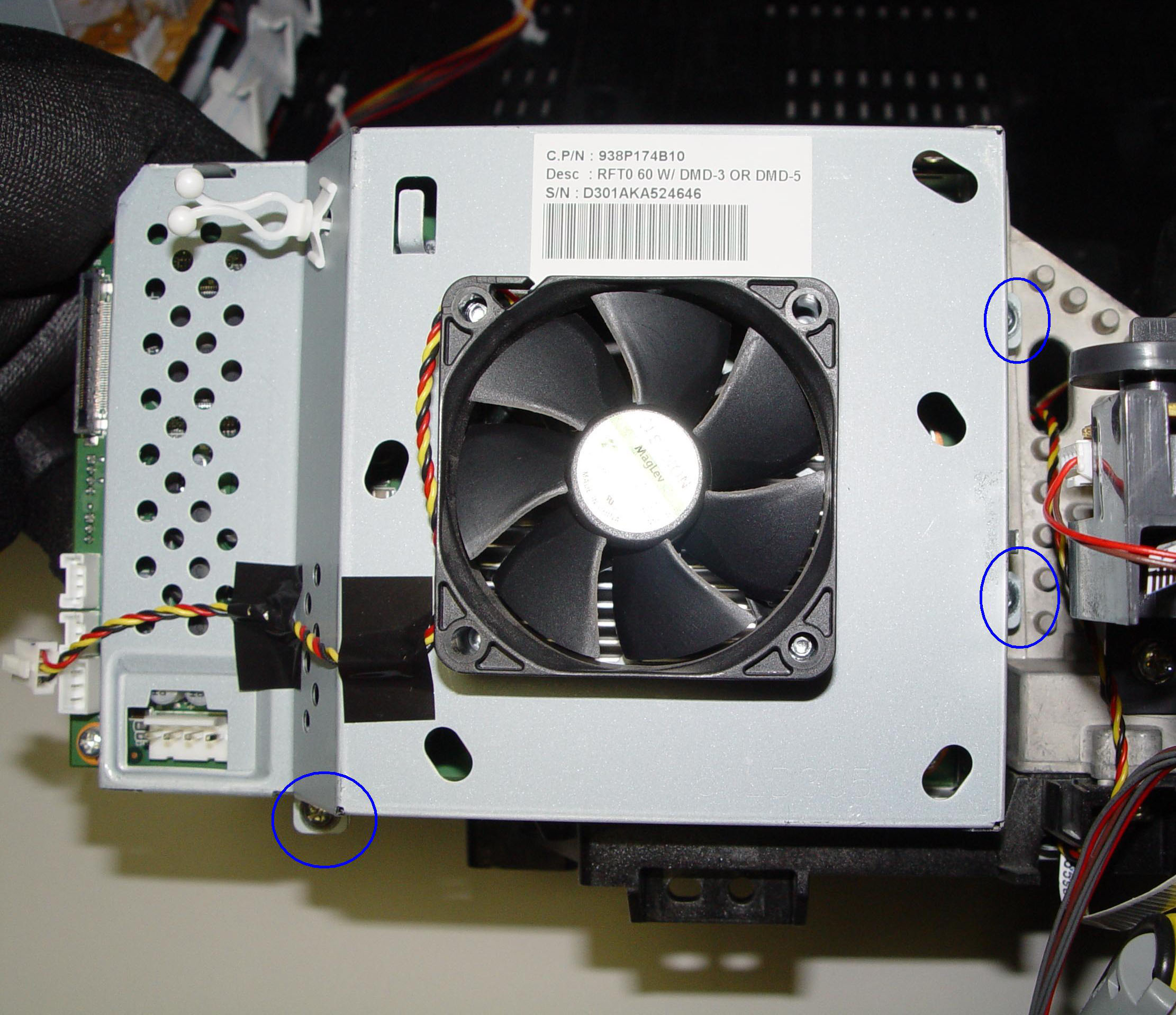
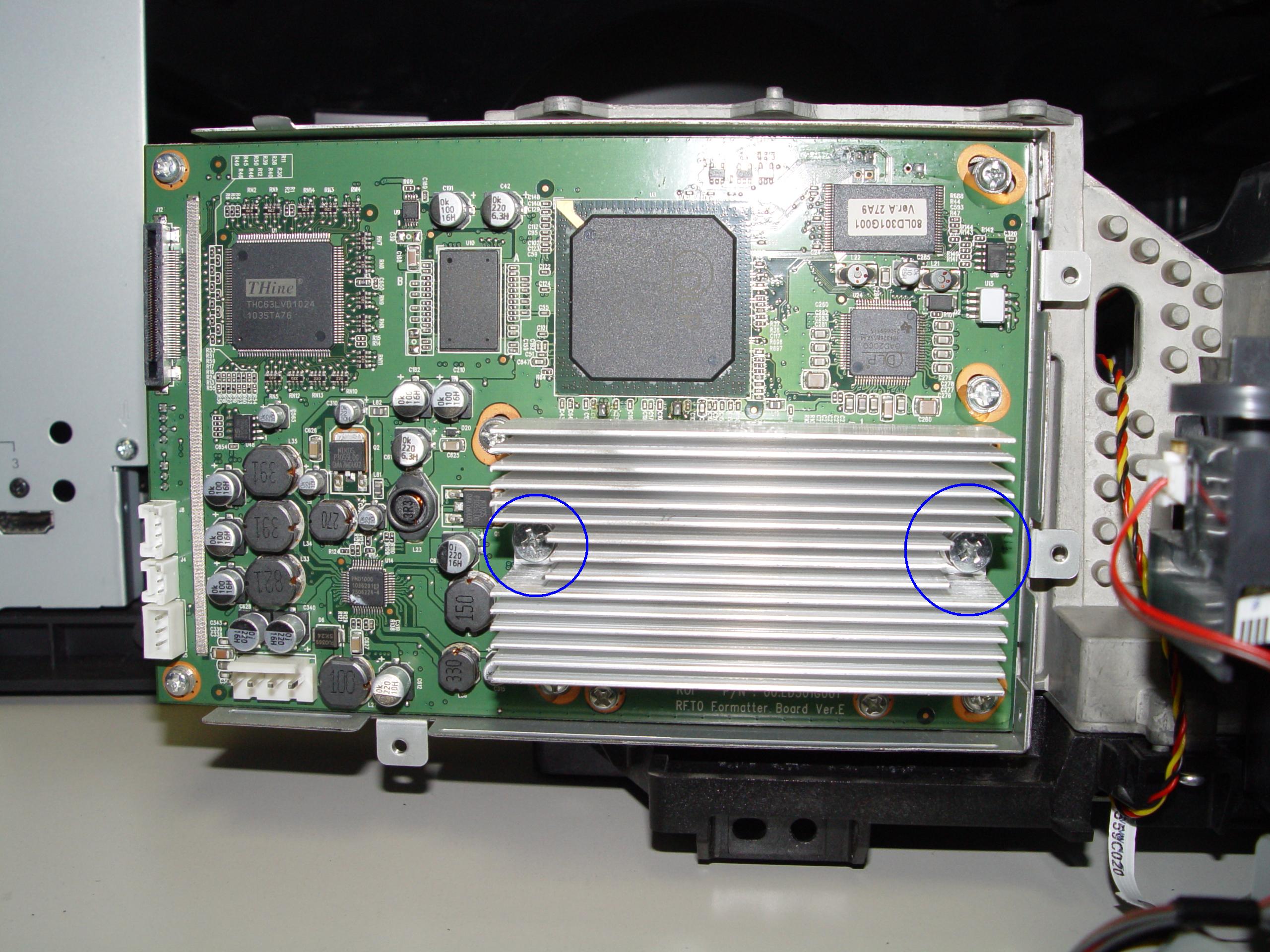
Step 9: Loosen the 3 screws holding the cooling unit/fan to the terminal board.
Step 10
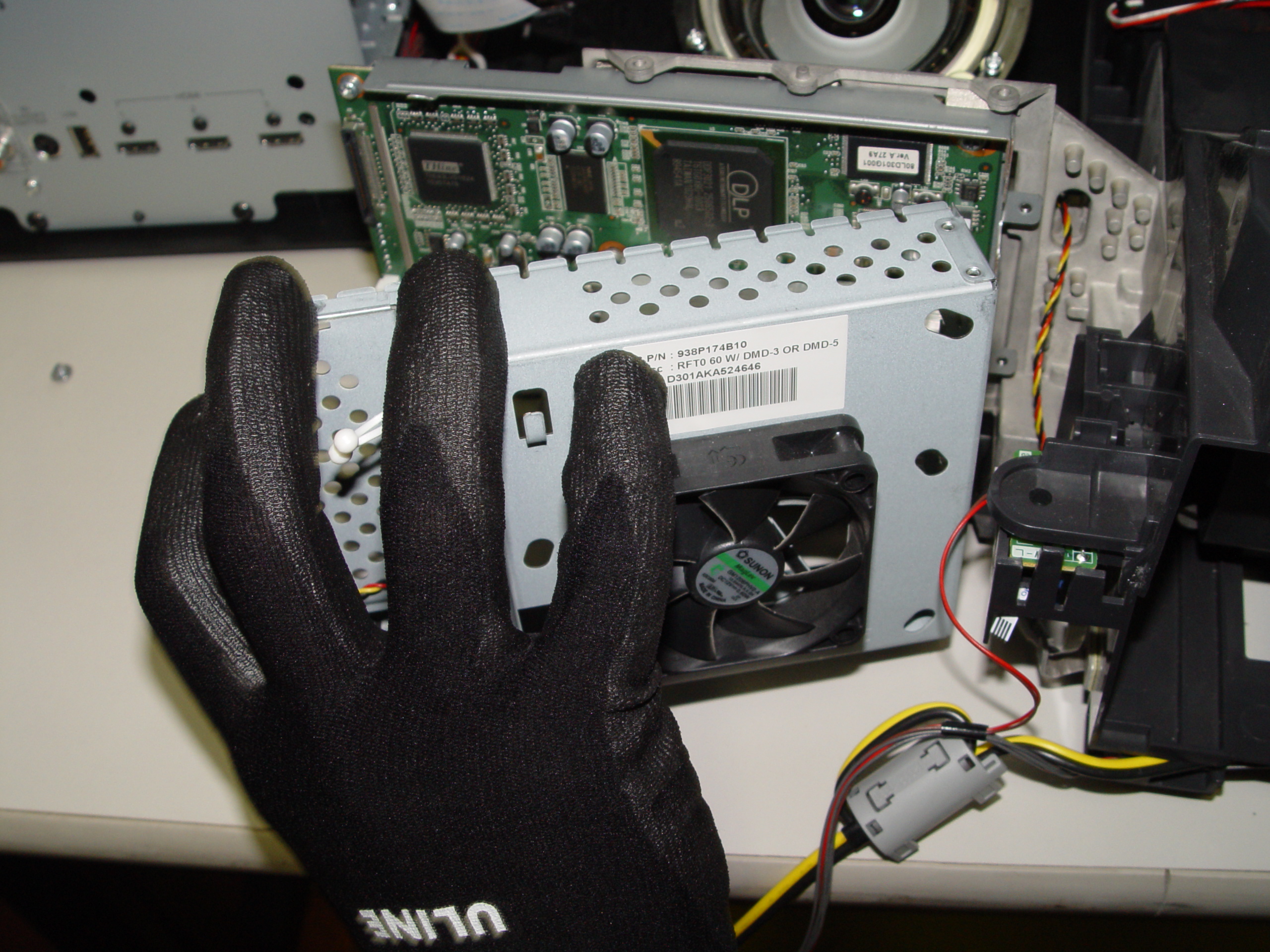
Step 10: Remove the cooling unit.
Step 11
Step 11: Loosen the 2 screws holding the terminal cover in place. (Good time to dust this section).
Step 12
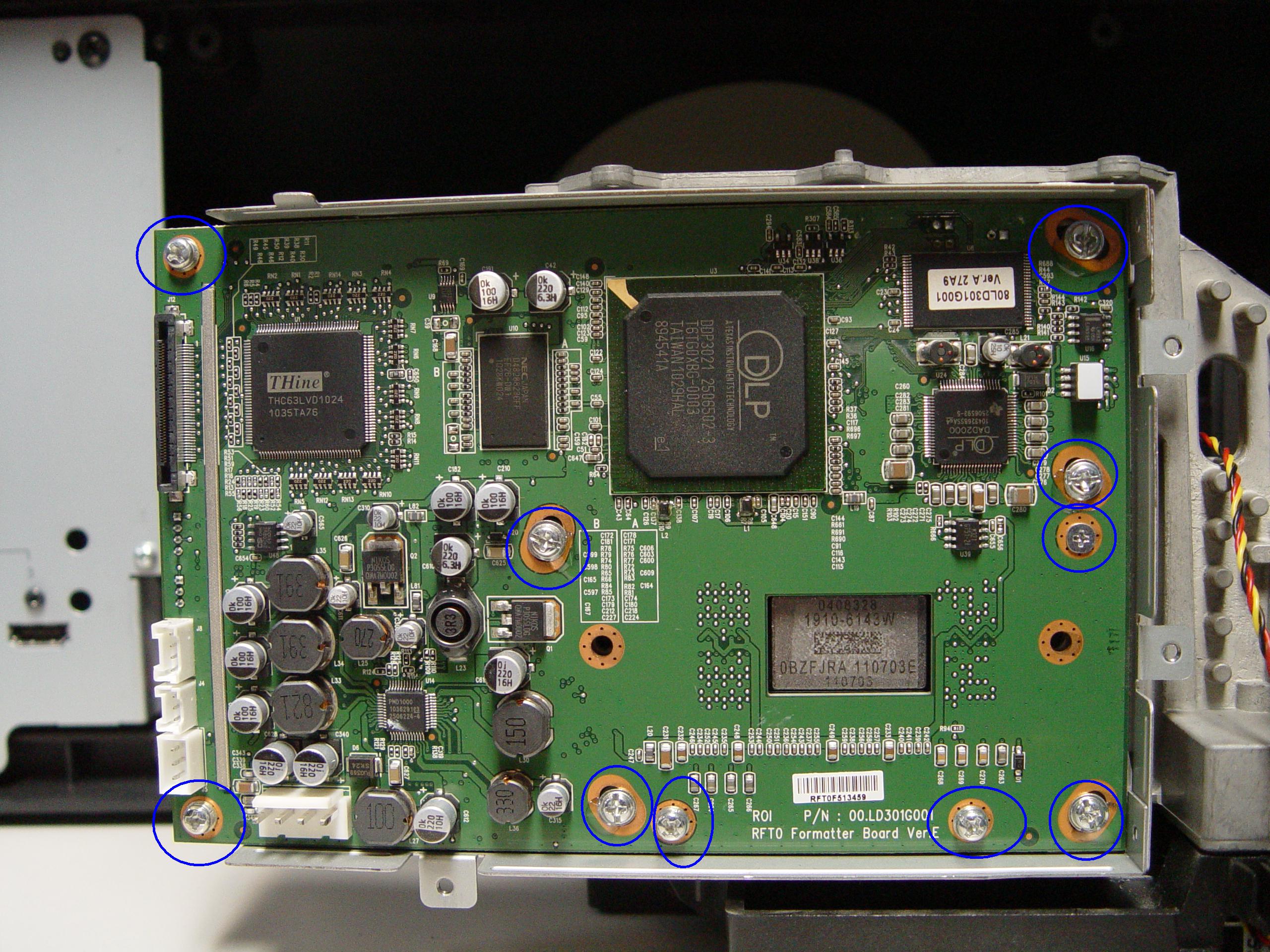
Step 12: Loosen the 10 screws holding the terminal in place.
Step 13
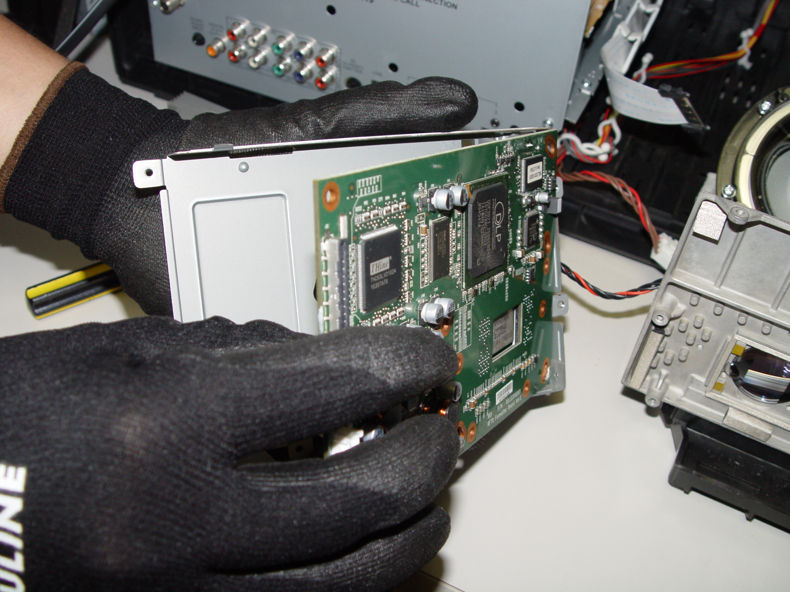
Step 13: Carefully pop the terminal out of its holder.
Step 14
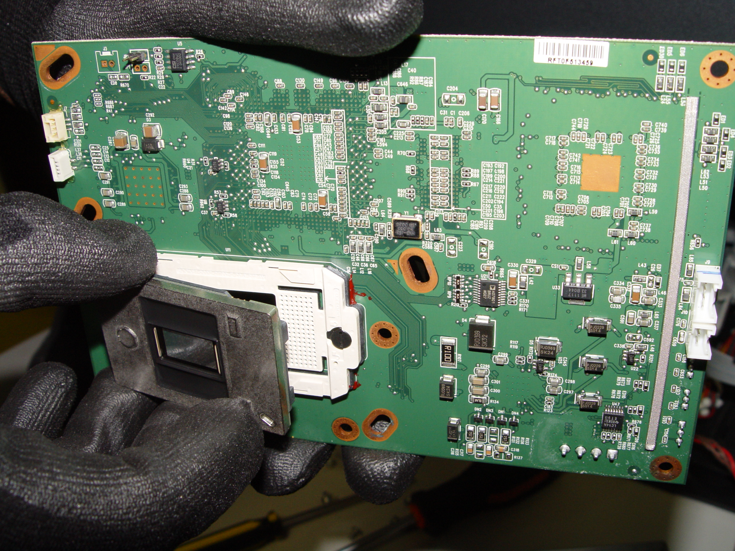
Step 14: Unlock the old DLP Chip from the terminal. You may need to loosen the screw on the side or use a flat edged screwdriver to pop it out.
Step 15
Step 15: Place the new DLP chip into place. Handle the DMD DLP CHIP only by the edges because it is very sensitive to antistatic electricity.
Step 16
Step 16: Put the terminal back into its holder.
Step 17
Step 17: Tighten the 10 screws holding the terminal in place.
Step 18
Step 18: Tighten the 2 screws on terminal board’s cover.
Step 19
Step 19: Put the fan unit back on.
Step 20
Step 20: Tighten the 3 screws holding the cooling unit/fan to the terminal board.
Step 21
Step 21: Reconnect the cables connecting the color wheel.
Step 22
Step 22: Reconnect the cable between the terminal board and lamp.
Step 23
Step 23: Replace the color wheel protective cover and tighten the 3 screws.
Step 24
Step 24: Re-connect all the cables running from the terminal board and light engine.
Step 25
Step 25: Carefully place the light engine back inside the unit. Tighten the 3 holding the terminal board and light engine in place.
Step 26
Step 26: Put the back panel back onto the TV.
Step 27
Step 27: Tighten all the screws on the back panel. Enjoy your crisp, clear picture on your Mitsubishi WD-65735 RPTV.
Learn more about your Mitsubishi WD-65735 RPTV:
Find this new Mitsubishi/Toshiba 4719-001997 DLP Chip 1910-6143W on Amazon.
The photos you show in this tutorial are NOT the Mitsubishi WD-65735. I performed step one, and the inside of my TV (which is a confirmed WD-65735 as proven by label on the back) does not have the layout shown in this tutorial, and in fact, is not even close. Perhaps you mistakenly posted the incorrect tutorial for WD-65735?
Hi Walter,
Sorry the blog was not helpful. The photos were more of just a guideline. If you head over to our forum and sign up, you can post a message asking for the specific photos. There should be someone on the forum who can help. There is a large community of experts that are ready and willing to help you get your chip changed and any other help your need.
I’ll ask someone from our office to look into getting the photos as well. Thanks for letting us know.
Regards,
Shelagh
E Z Peezee, sort of. Found that even though I have a WD-65735 the screw counts and locations were different than these instructions, especially in the box and circuit board around the chip I was replacing. Figured it out and now have a running TV with no “stars” on the screen.
Thanks,
rj
Mitsubishi product wide DVD chip failure covered by Mitsubishi call their customer service my repair total cost was $200 as Mitsubishi has contracted with local TV repairman at this set cost my 2009 TV was just repaired for $200