
Install new Mitsubishi WD-65736 DLP Chip

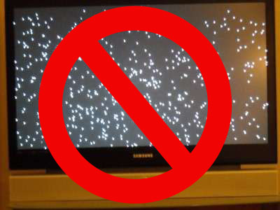
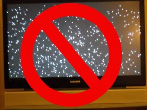
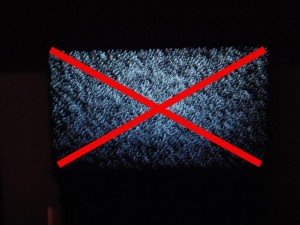
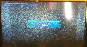
Banish white dots on your Mitsubishi WD-65736 screen by replacing the 4719-001997 DLP Chip.
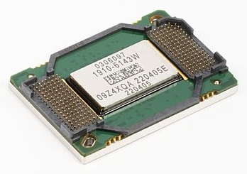
The white spots on your Mitsubishi WD-65736 are caused by the DLP chip being worn out. Known as Mitsubishi white death syndrome, this problem can be solved by installing a new Mitsubishi/Toshiba 4719-001997 DLP Chip 1910-6143W.
Note: These instructions can also be used for the following Mitsubishi models:
WD-57733, WD-57734, WD-57833, WD-60638, WD-60733,WD-60735, WD-60737,WD-60738, WD-60833, WD-60837, WD-60C8,WD-60C9, WD-65638,WD-65731, WD-65733,WD-65734, WD-65735, WD-65736, WD-65737, WD-65738,WD-65833,WD-65835,WD-65837, WD-65838,WD-65C8,WD-65C9, WD-73638, WD-73640, WD-73642, WD-73733, WD-73734, WD-73735, WD-73736,WD-73737, WD-73738, WD-73833, WD-73835,WD-73837,WD-73838, WD-73840, WD-73C11, WD-73C8, WD-73C9, WD-75837, WD-82737, WD-82738, WD-82838, WD-Y657 WD-C657,WD-Y577.
Find this new Mitsubishi/Toshiba 4719-001997 DLP Chip 1910-6143W on Amazon and then follow our step-by-step visual guide.
Equipment needed
- Electric Philips screwdriver
- needle nose pliers or a 5mm nut driver
- antistatic gloves OR plastic gloves used with an antistatic wrist band
- soft cloth or brush
How to replace the 4719-001997 DLP Chip
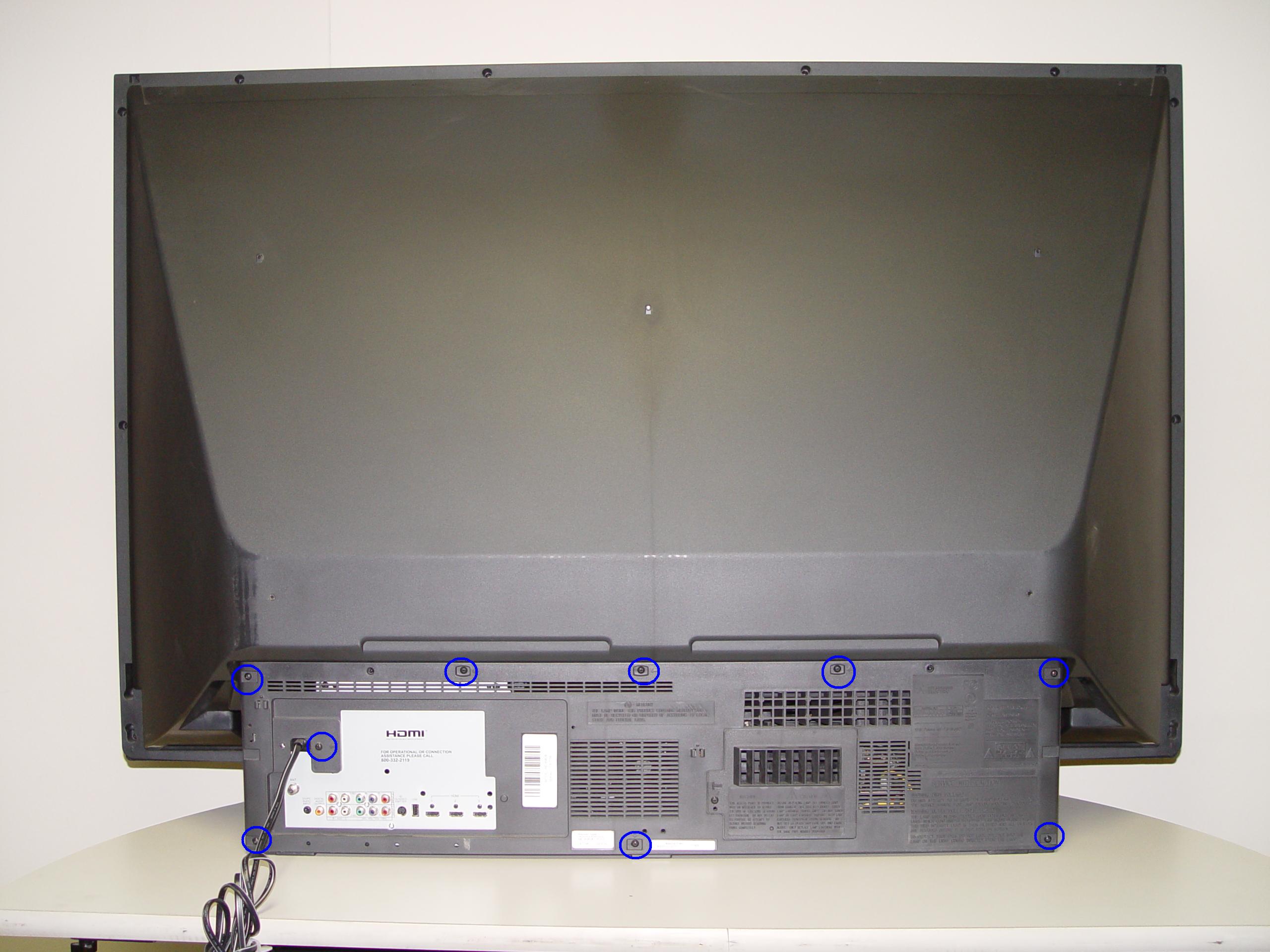
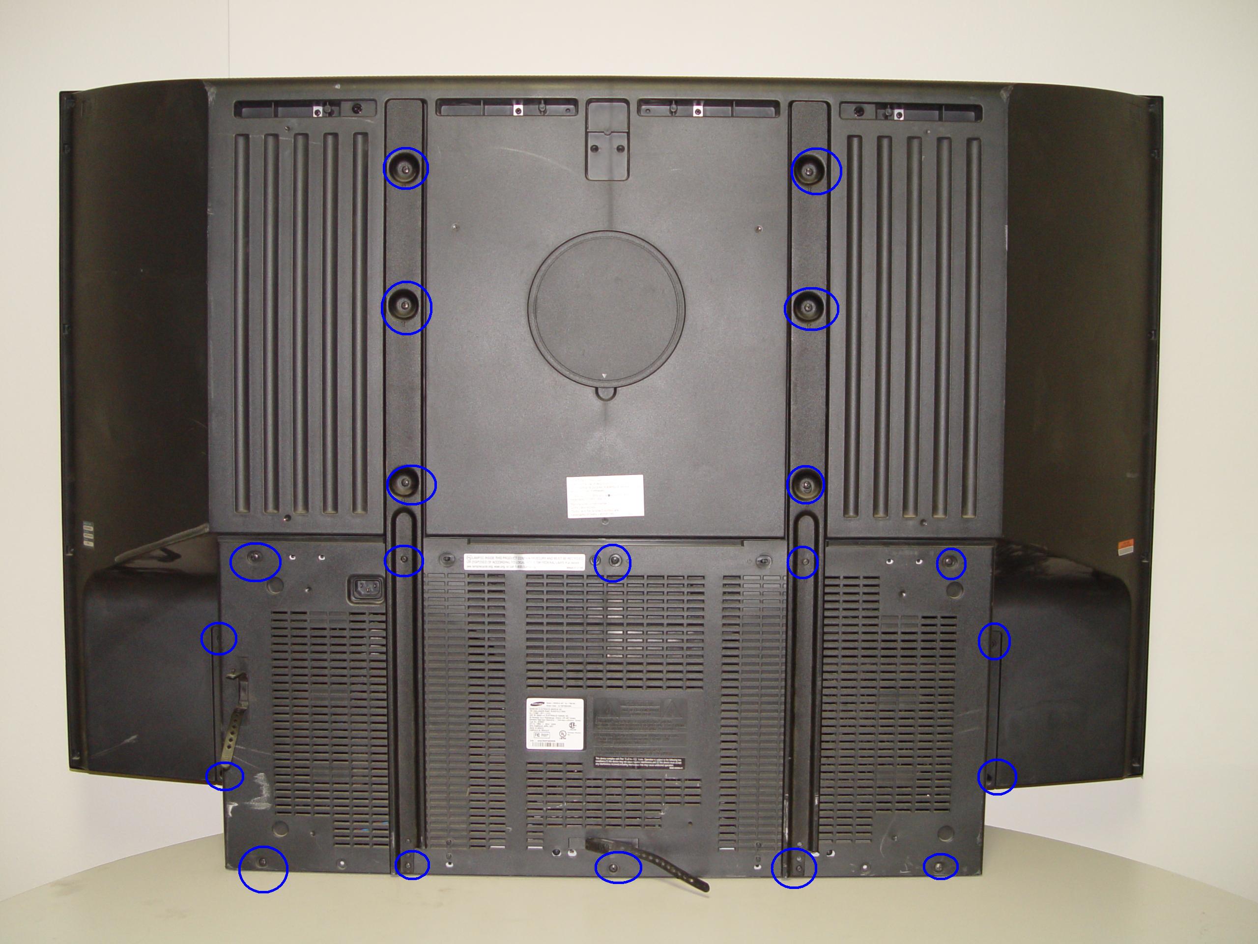
Step 1
Step 1: Put on the plastic gloves. Loosen all the screws found on the back panel.
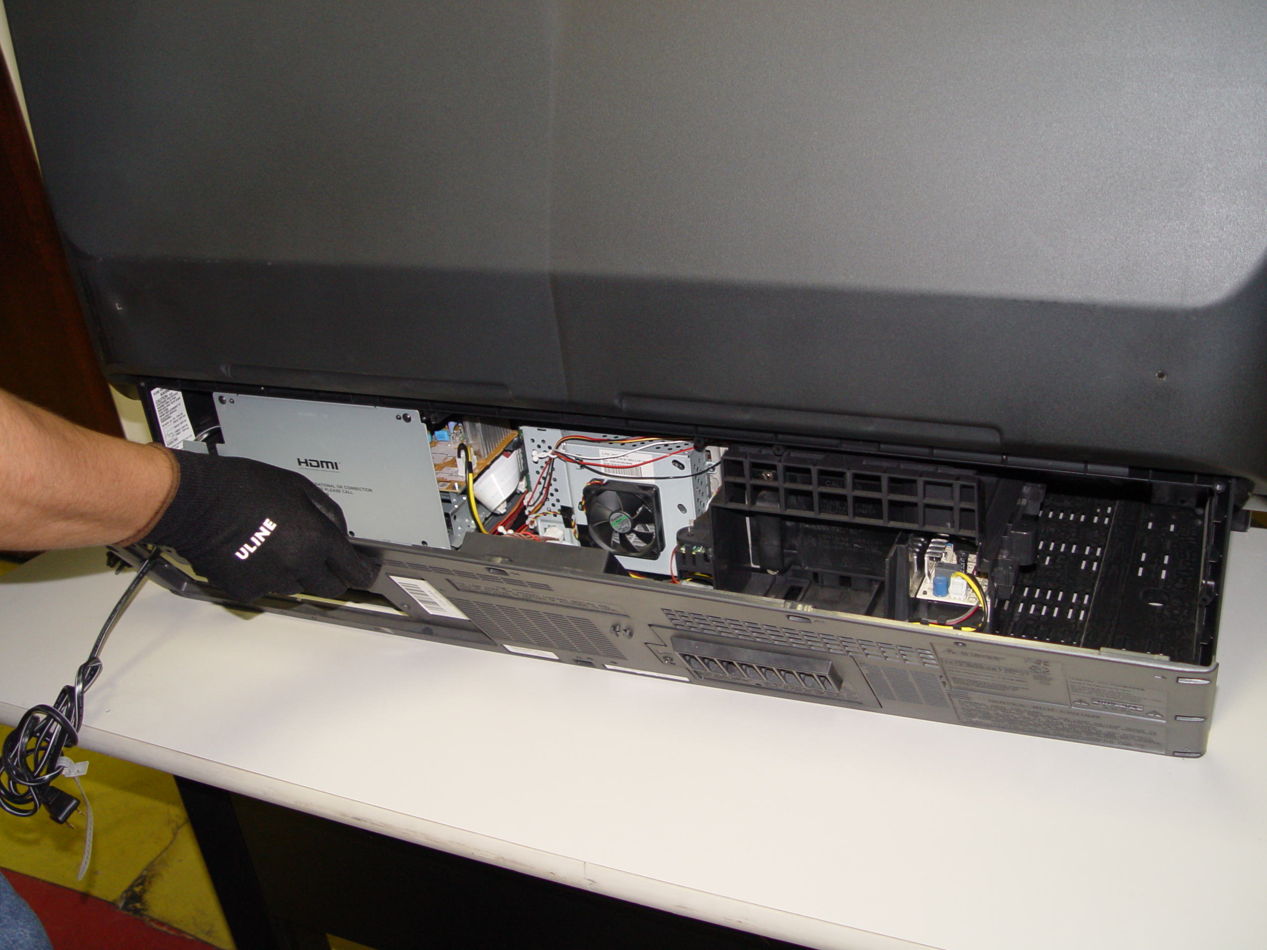
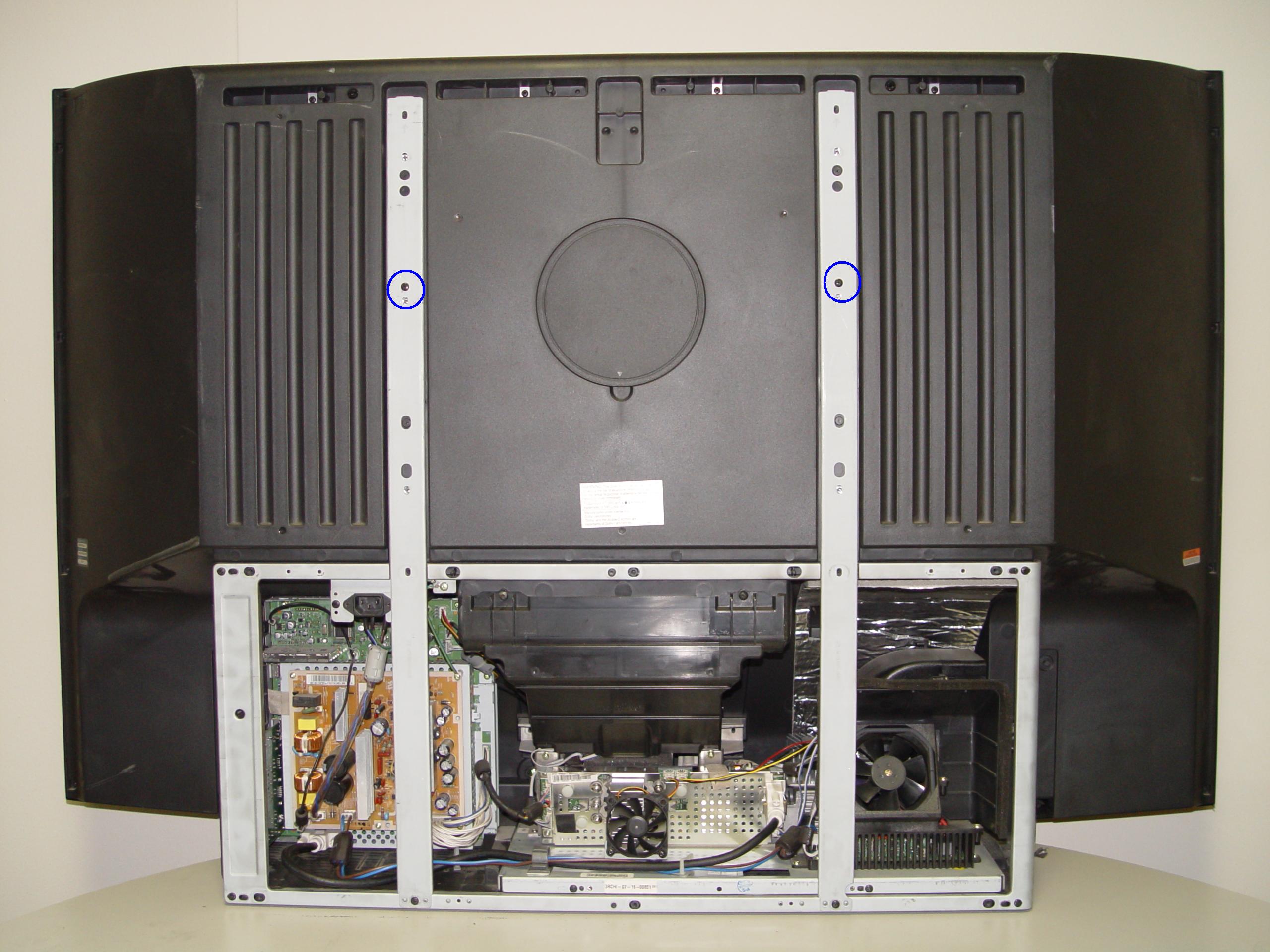
Step 2
Step 2: Put the screws to the side. Gently remove the back panel.
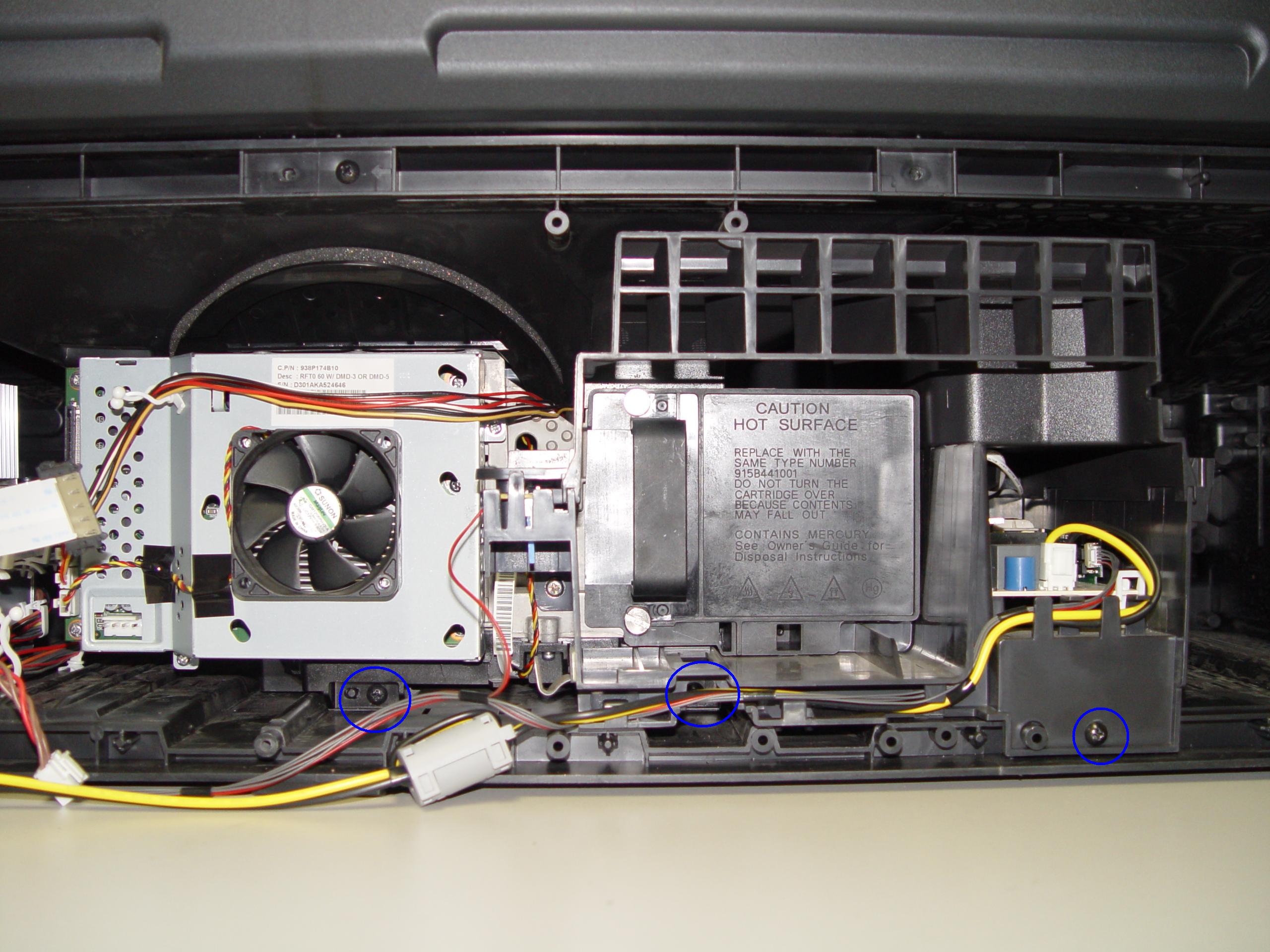
Step 3
Step 3: Remove the 3 screws holding the lamp engine in place.
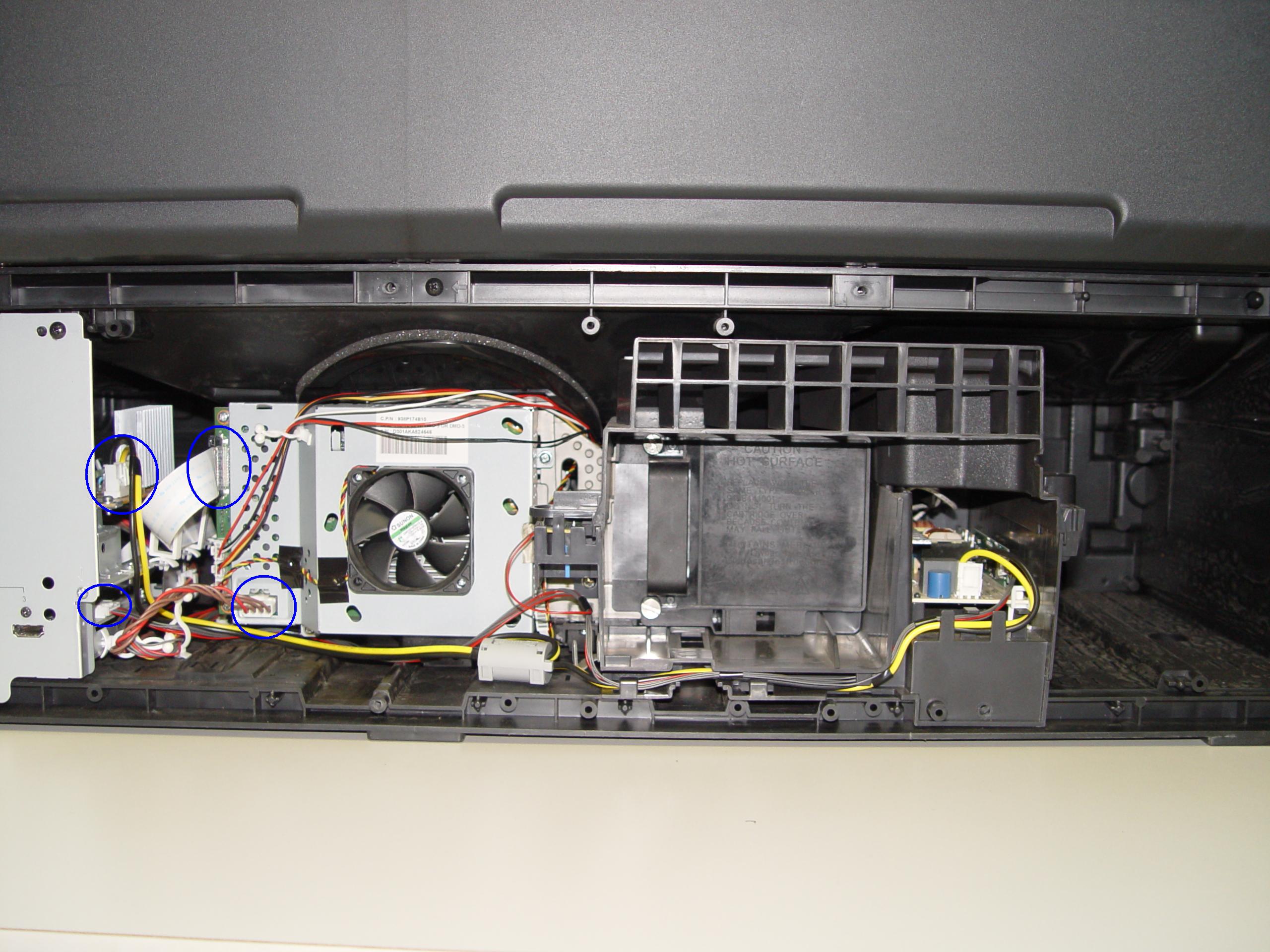
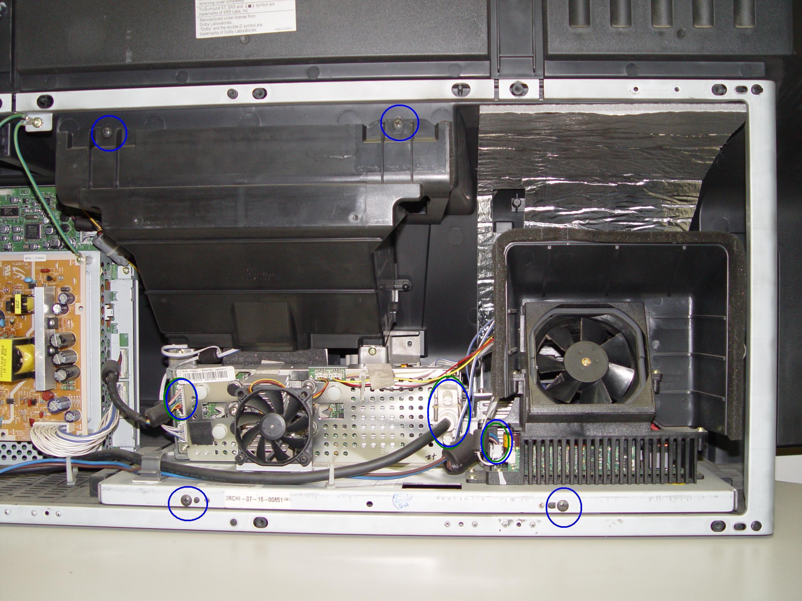
Step 4
Step 4: Disconnect all the connectors. Important: don’t yank any cables.
Step 5
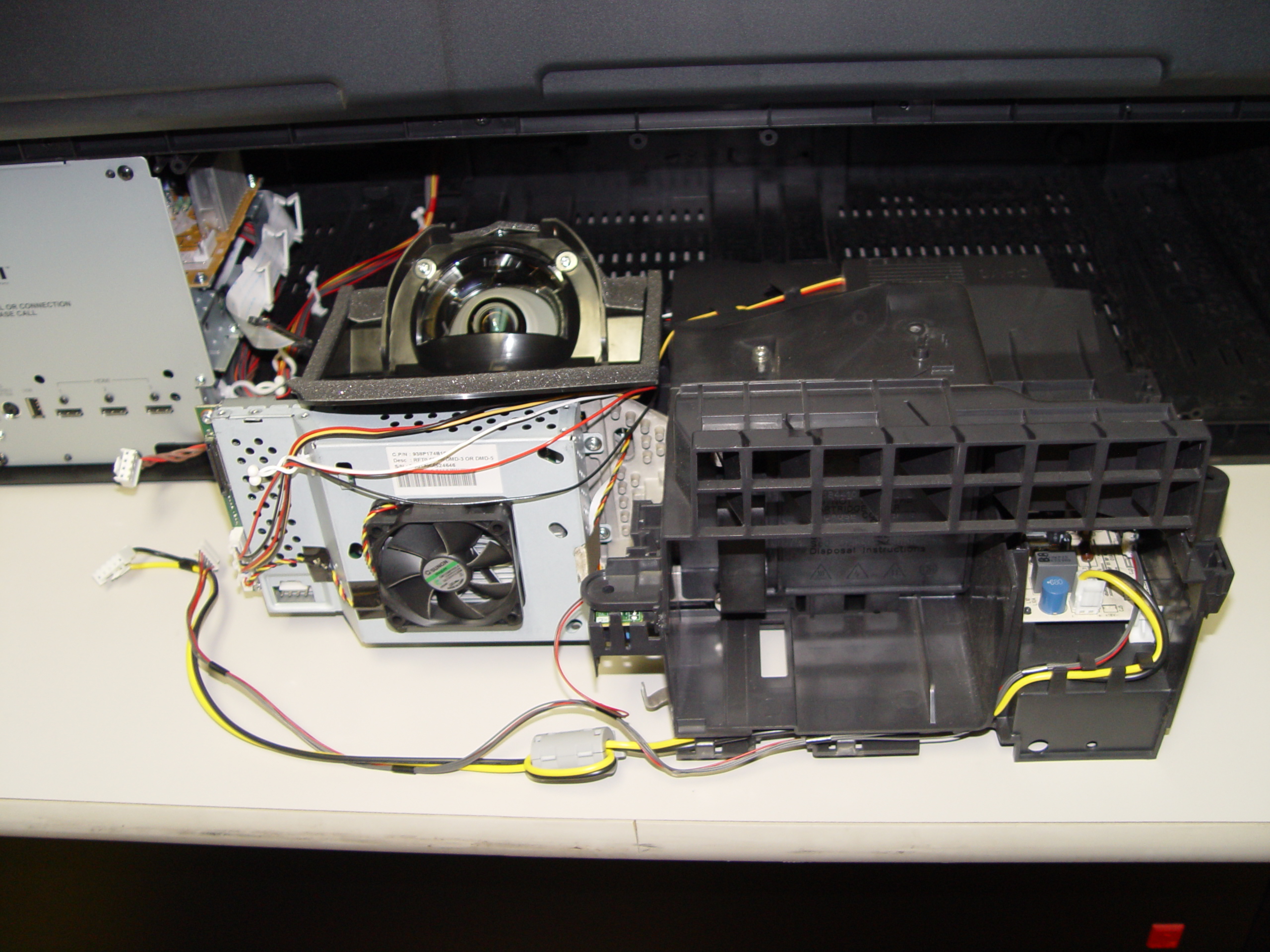
Step 5: Carefully slide the light engine from the cabinet.
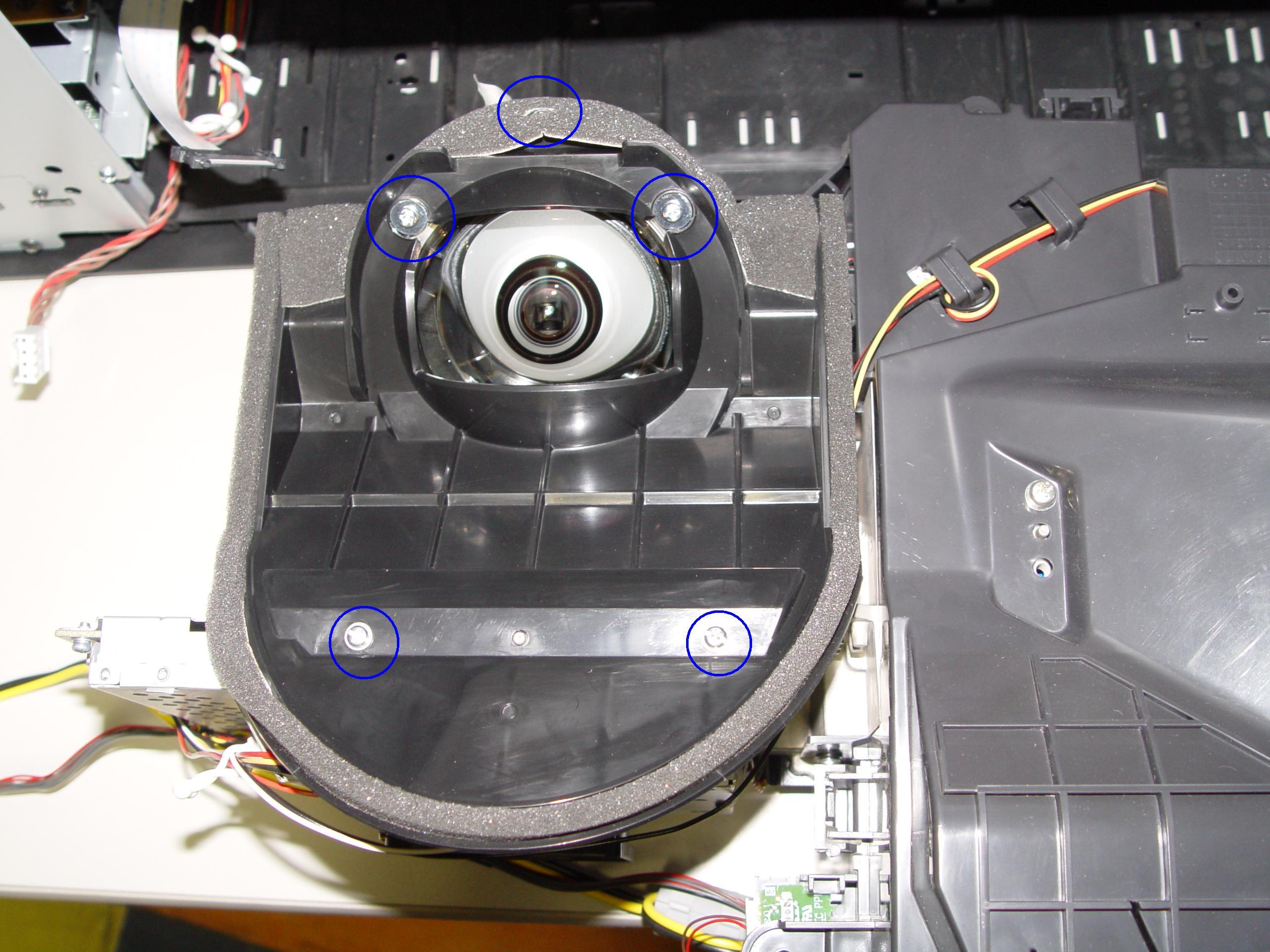
Step 6
Step 6: Remove the 3 screws holding the color wheel protective cover in it place. Avoid touching any of the optical components as this can affect the quality of your picture.
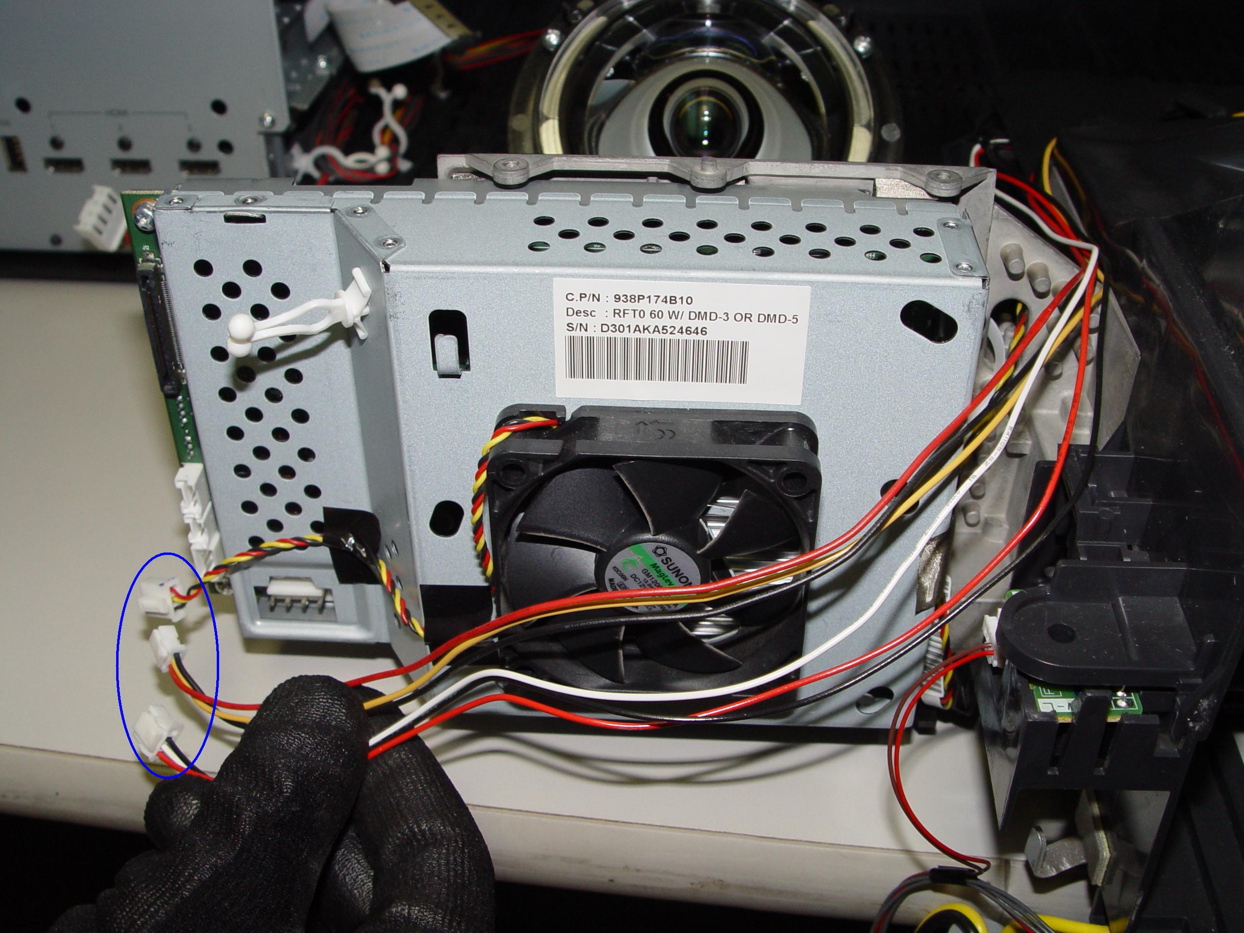
Step 7
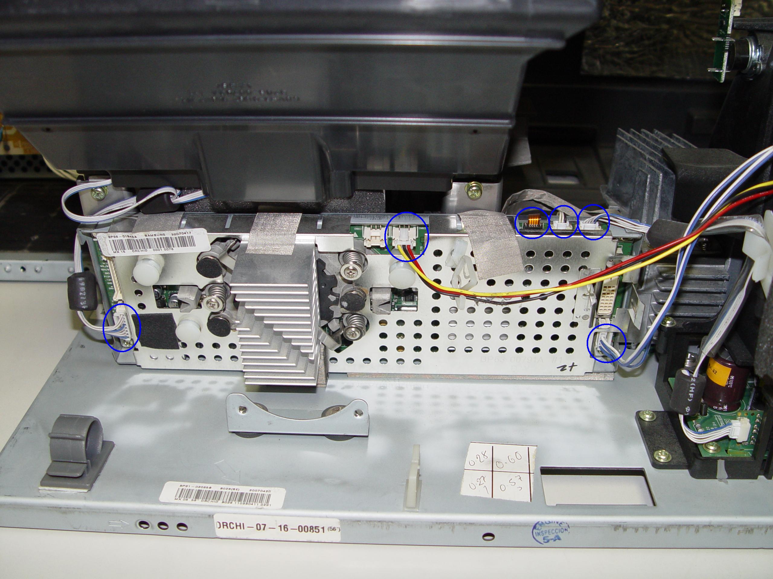
Step 7: Carefully disconnect the cable between the terminal board and lamp.
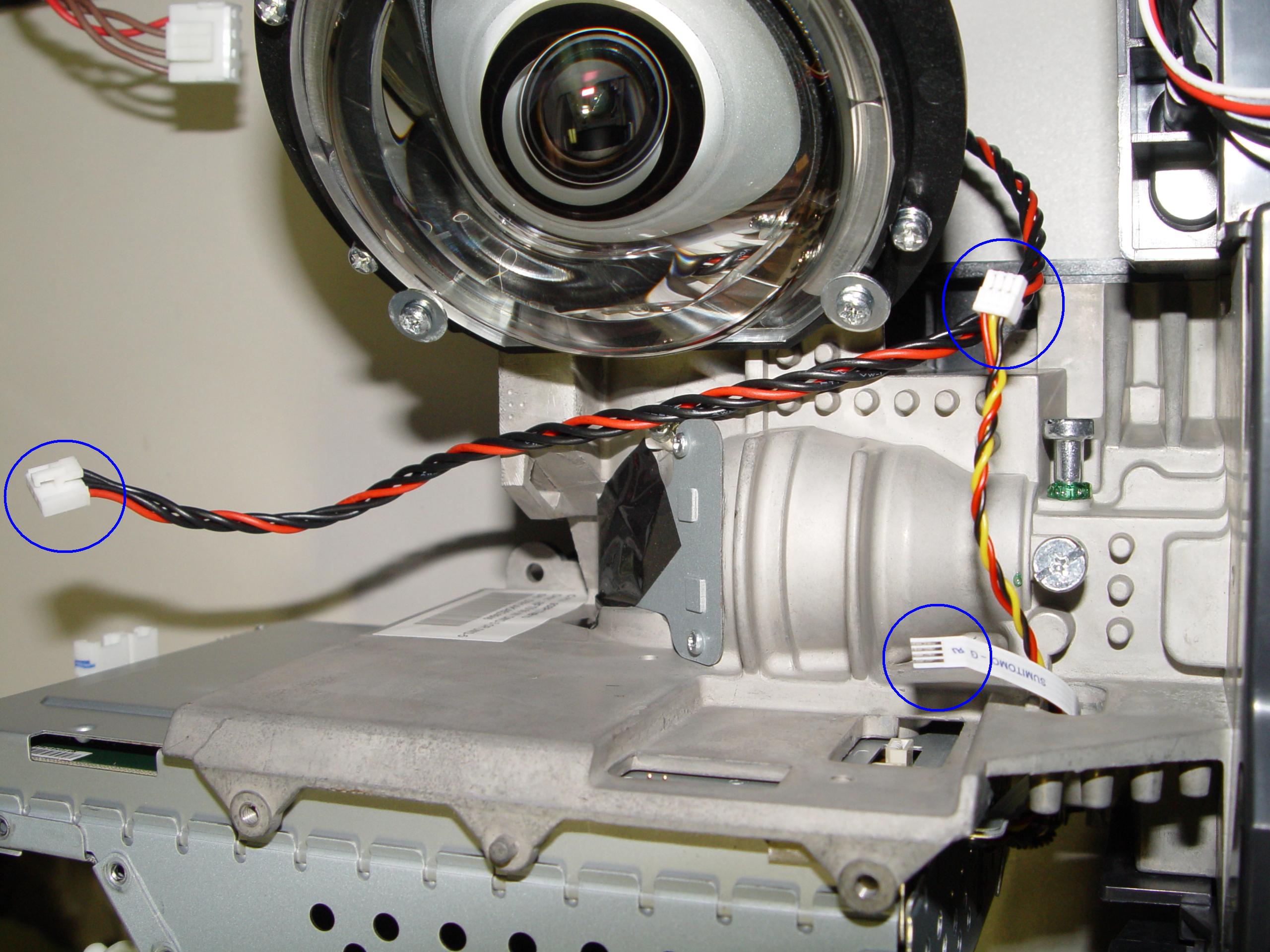
Step 8
Step 8: Disconnect the cables connecting the color wheel.
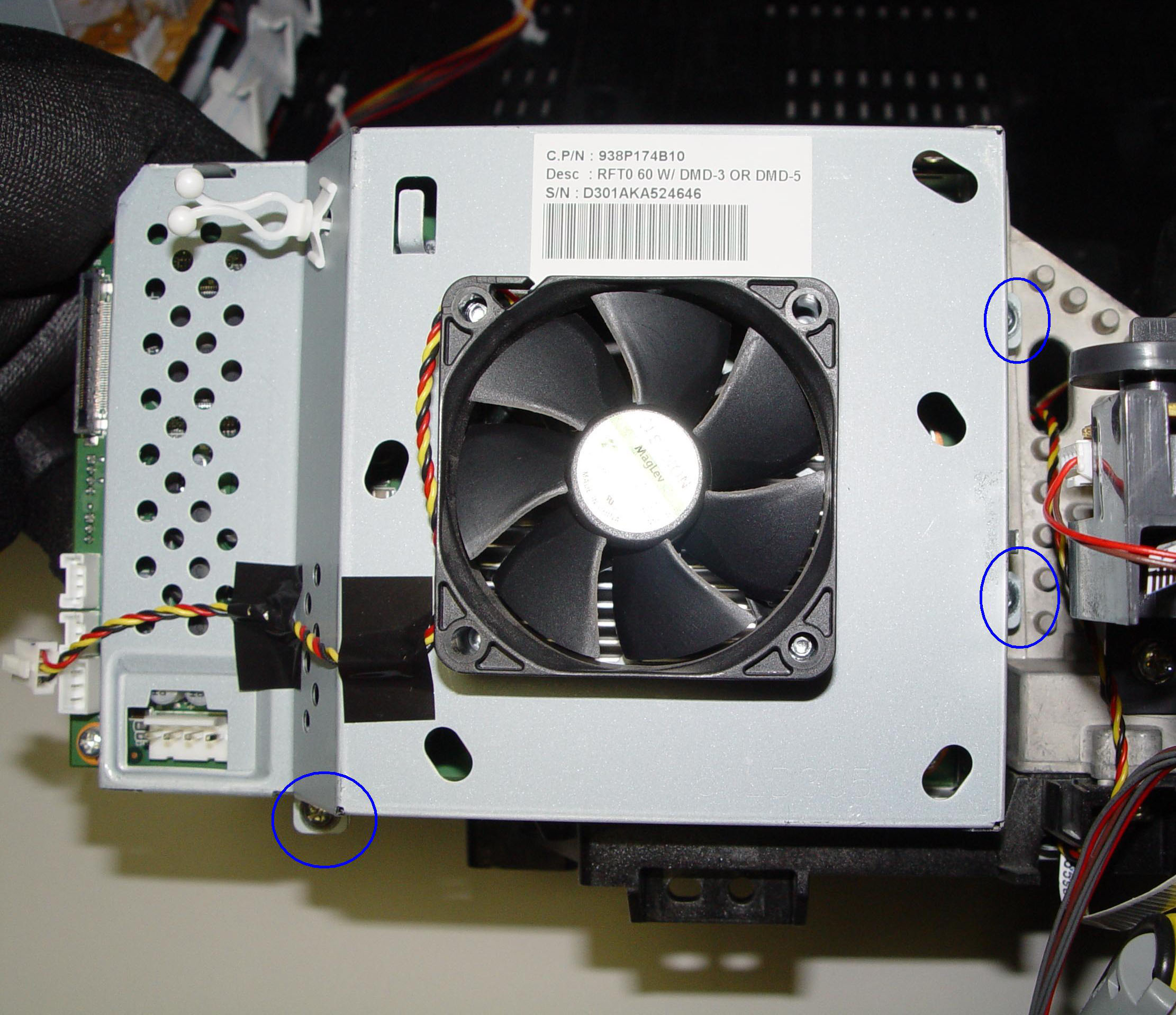
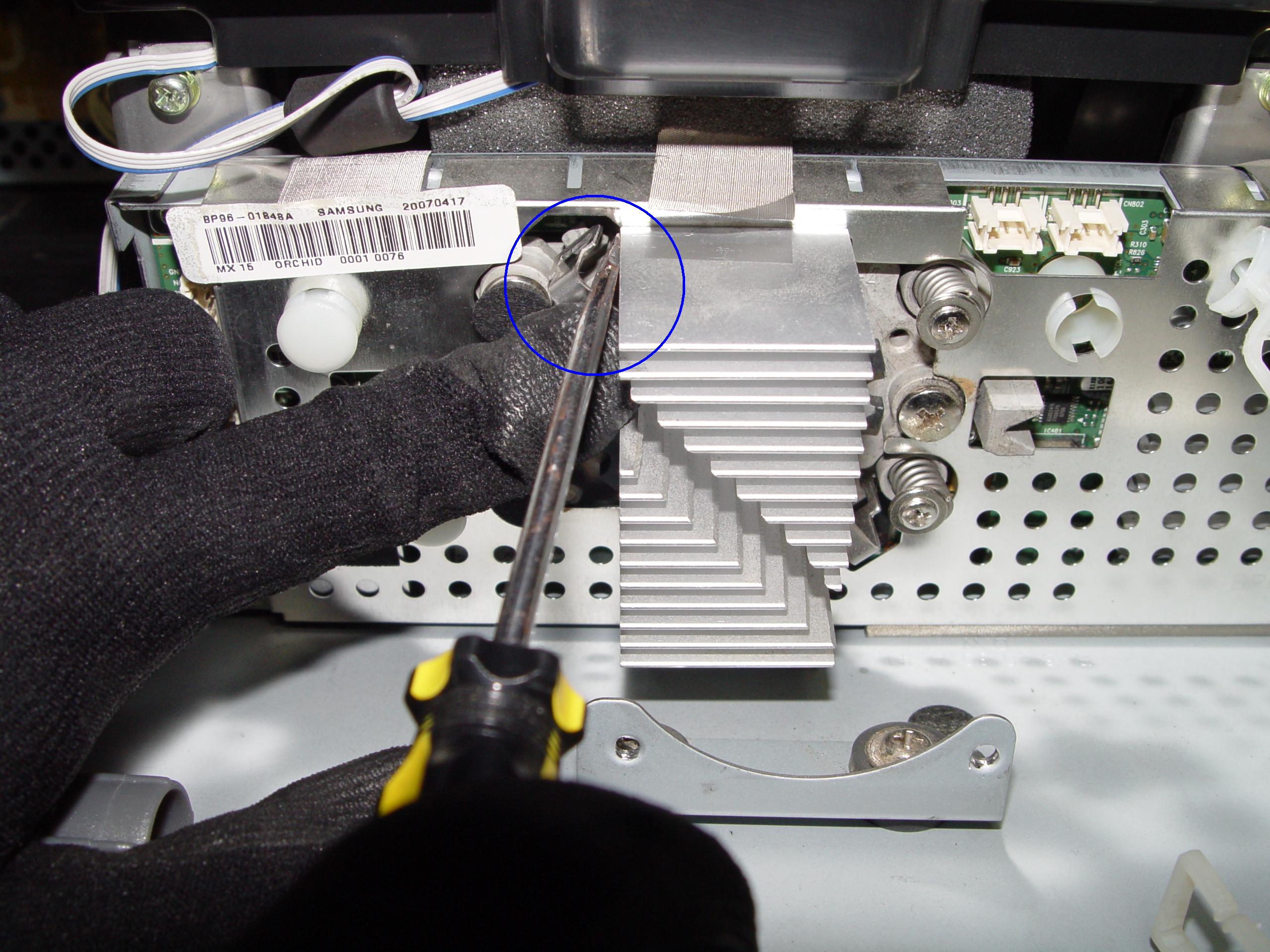
Step 9
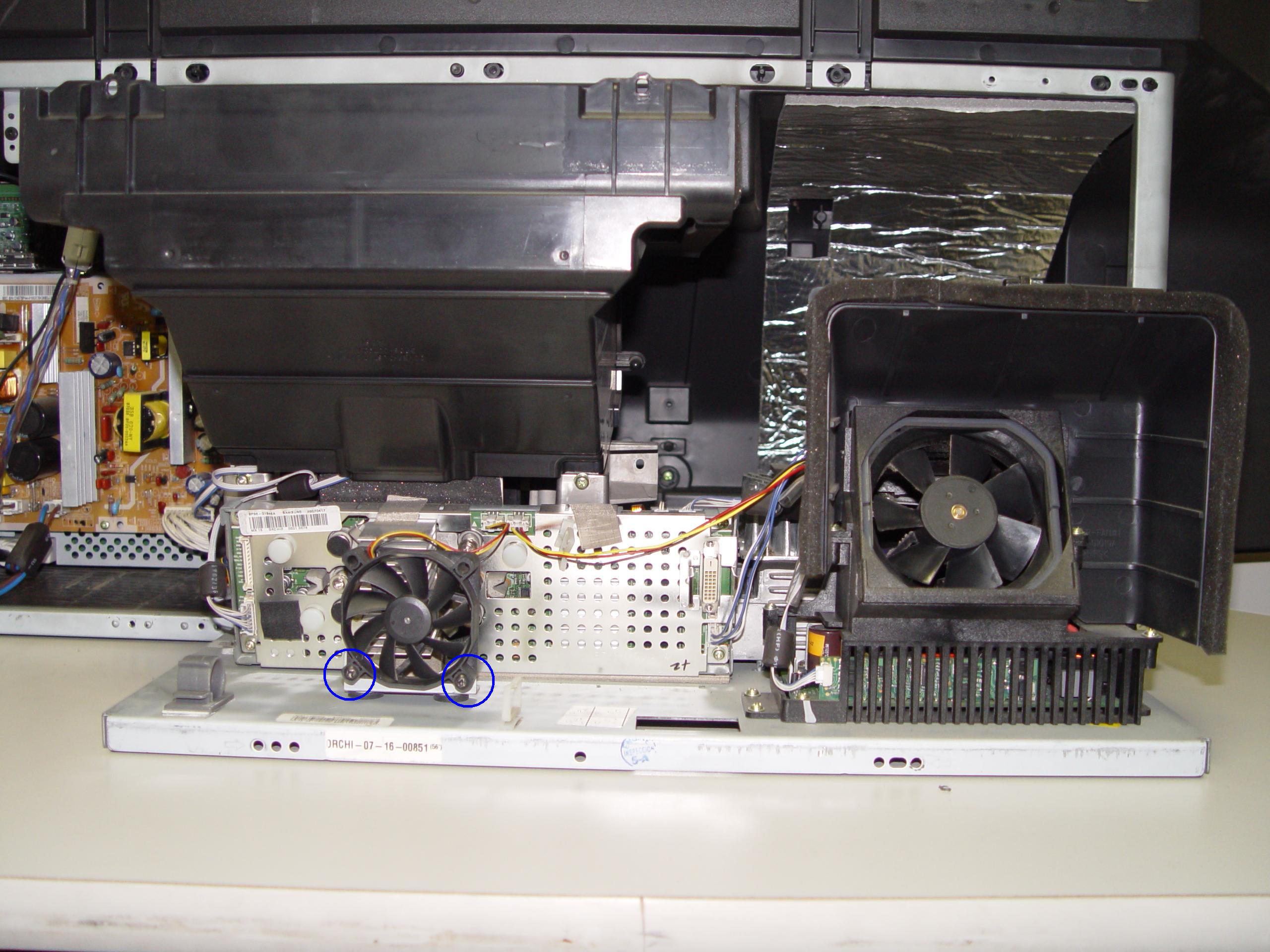
Step 9: Loosen the 3 screws holding the cooling unit/fan to the terminal board.
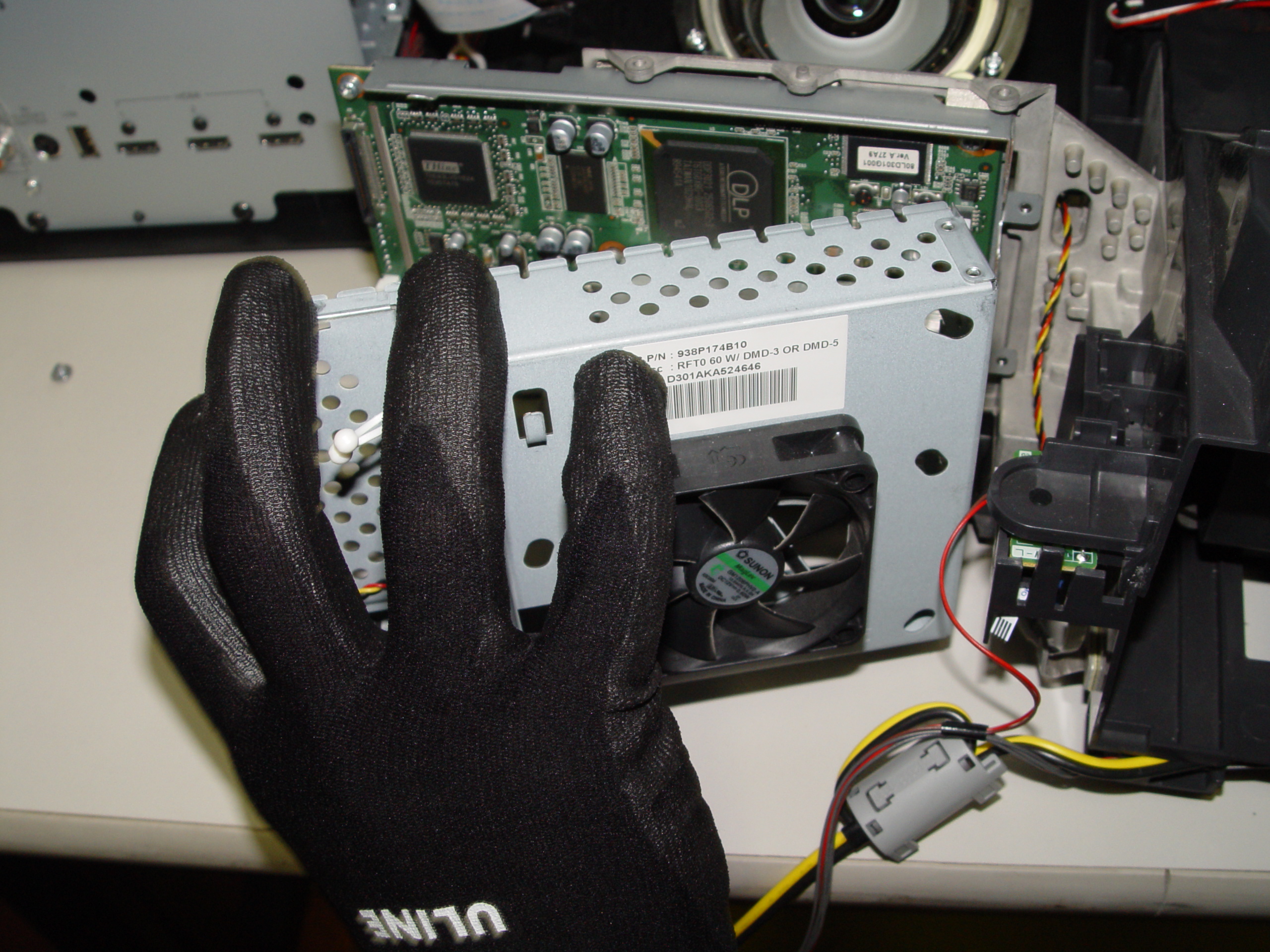
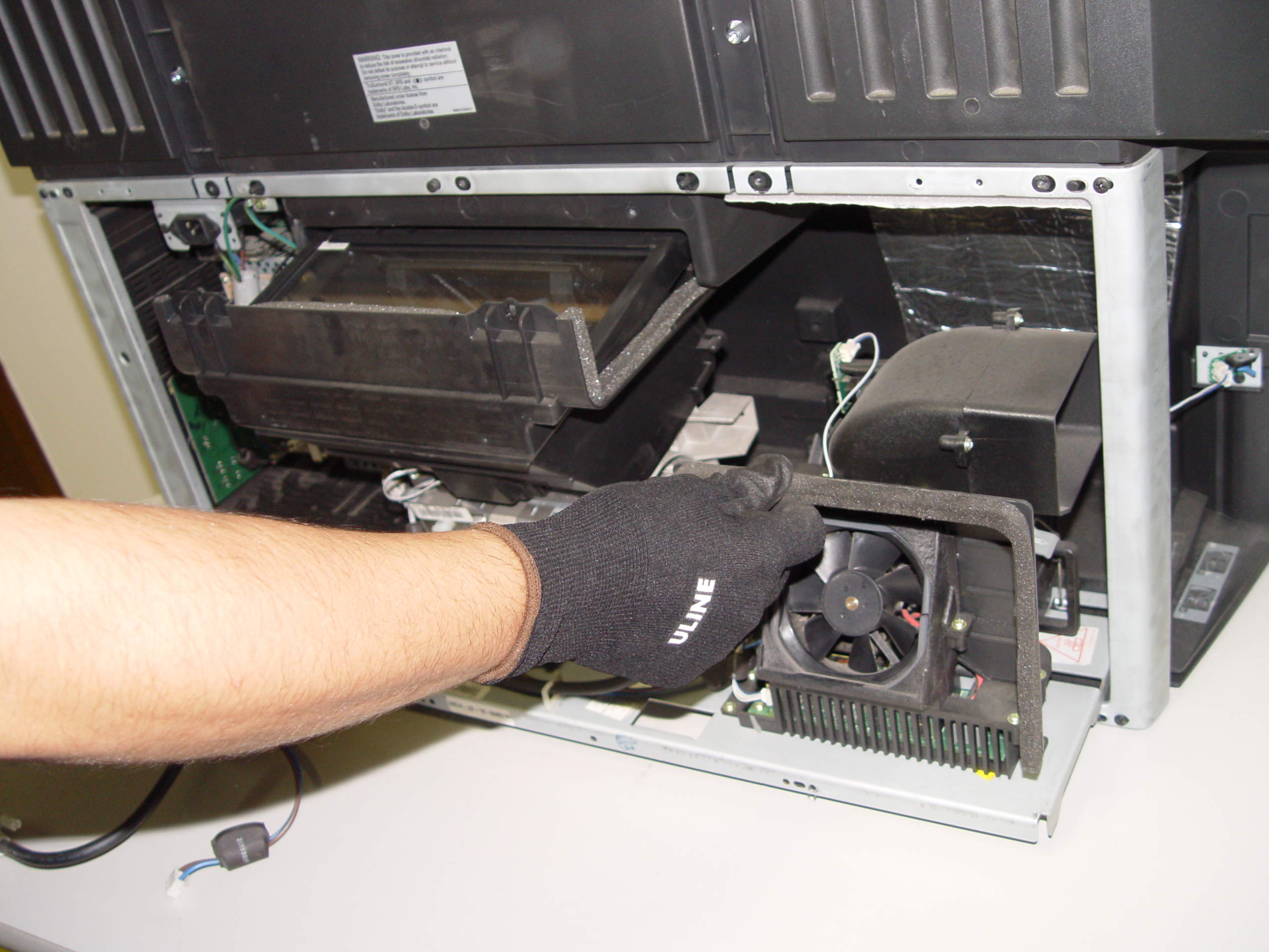
Step 10
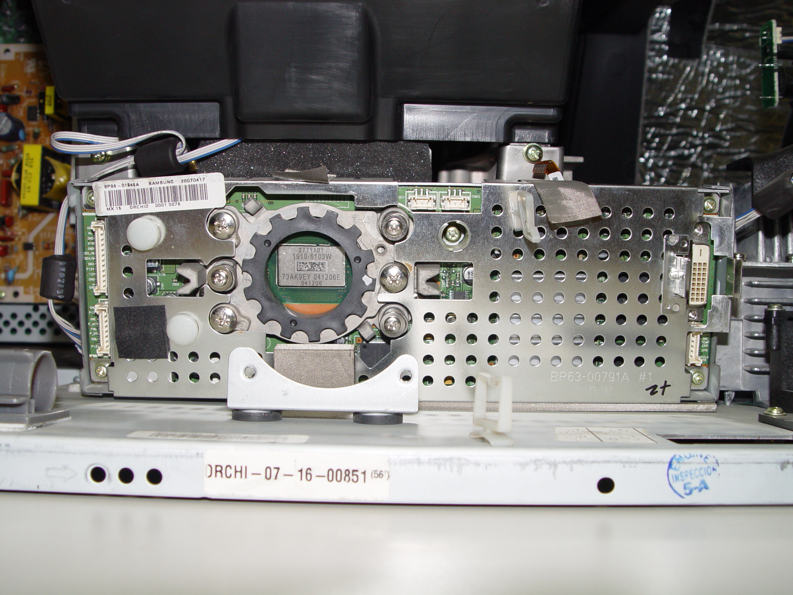
Step 10: Remove the cooling unit.
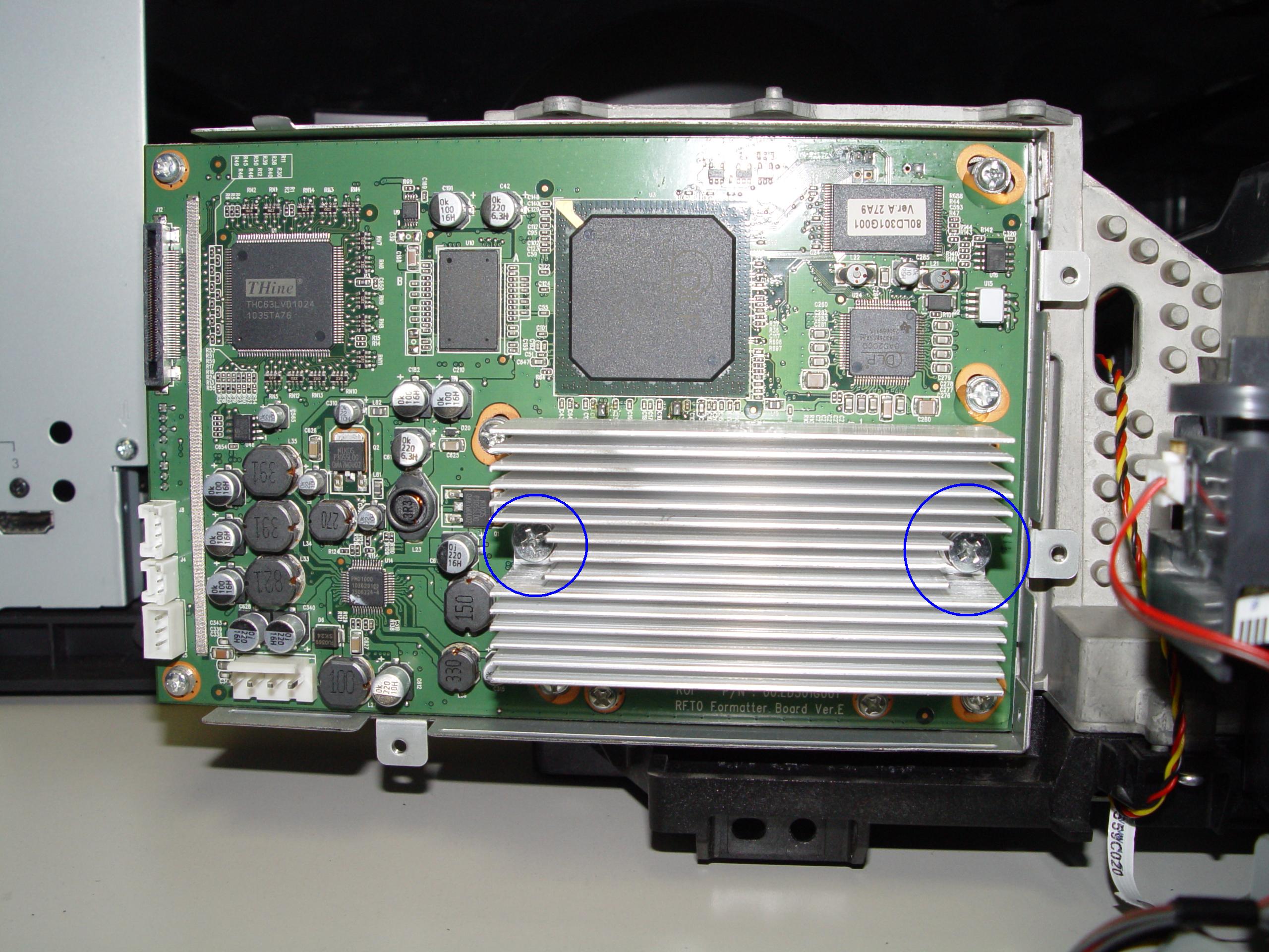
Step 11
Step 11: Loosen the 2 screws holding the terminal cover in place. (Good time to dust this section).
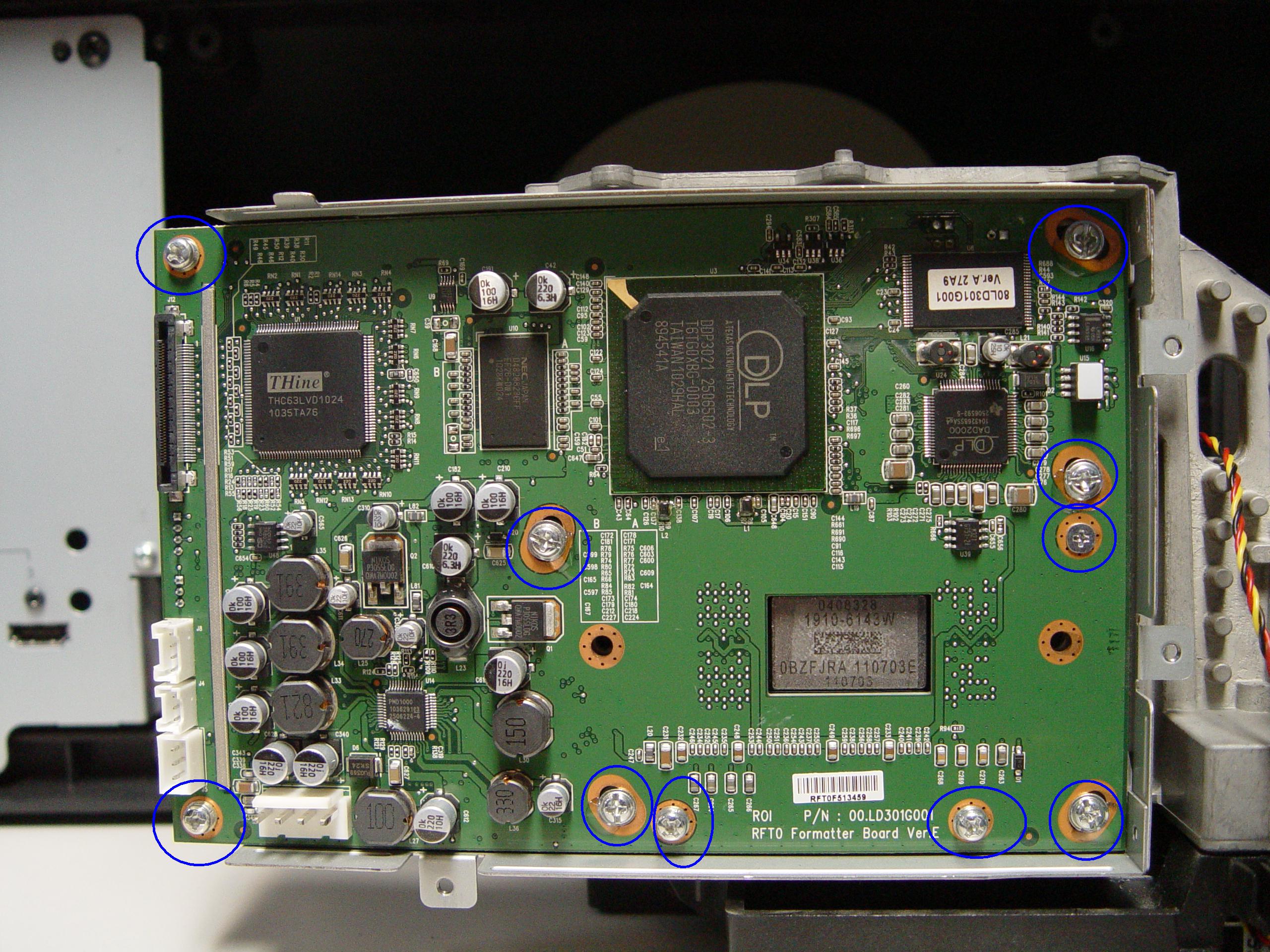
Step 12
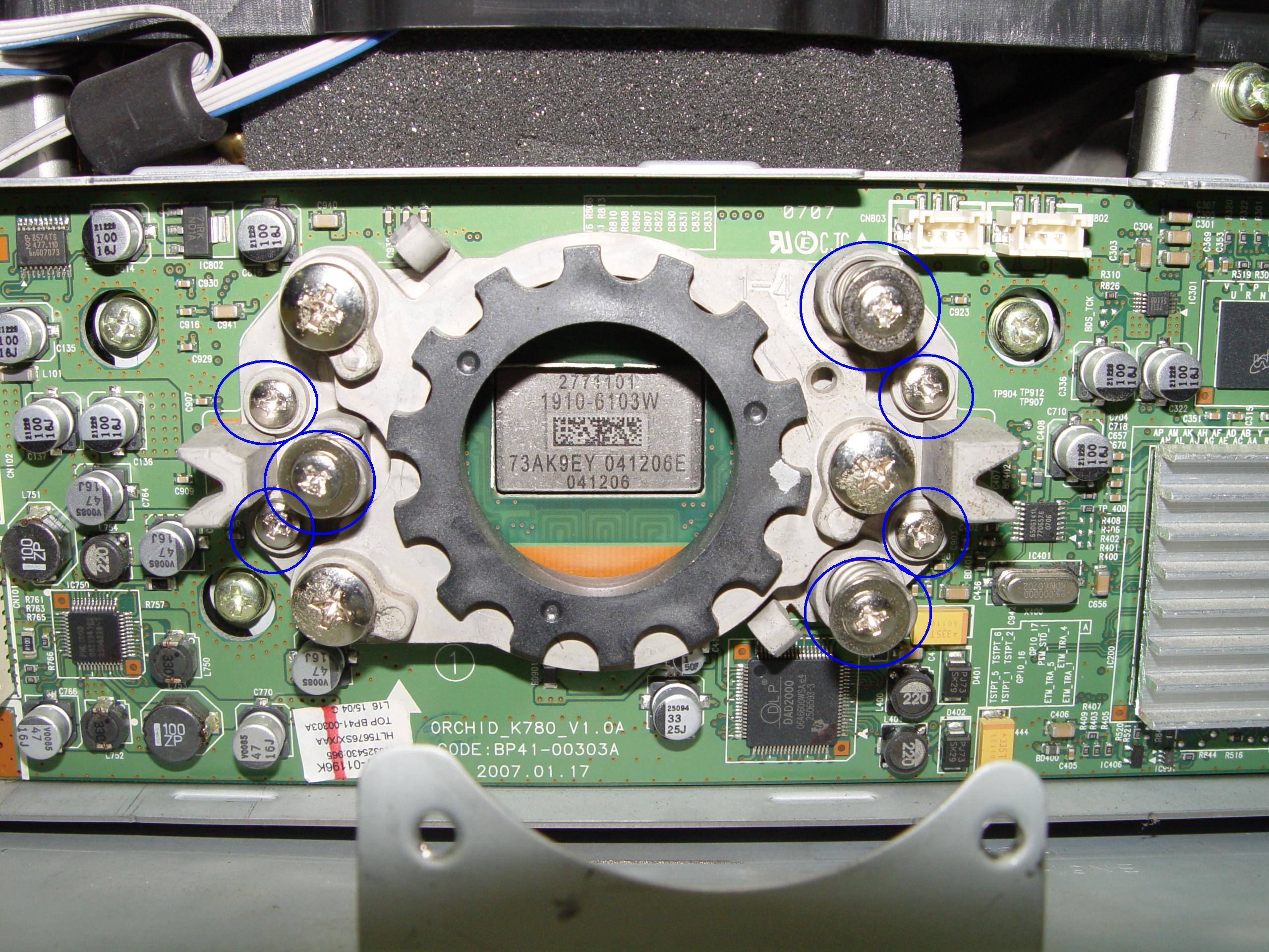
Step 12: Loosen the 10 screws holding the terminal in place.
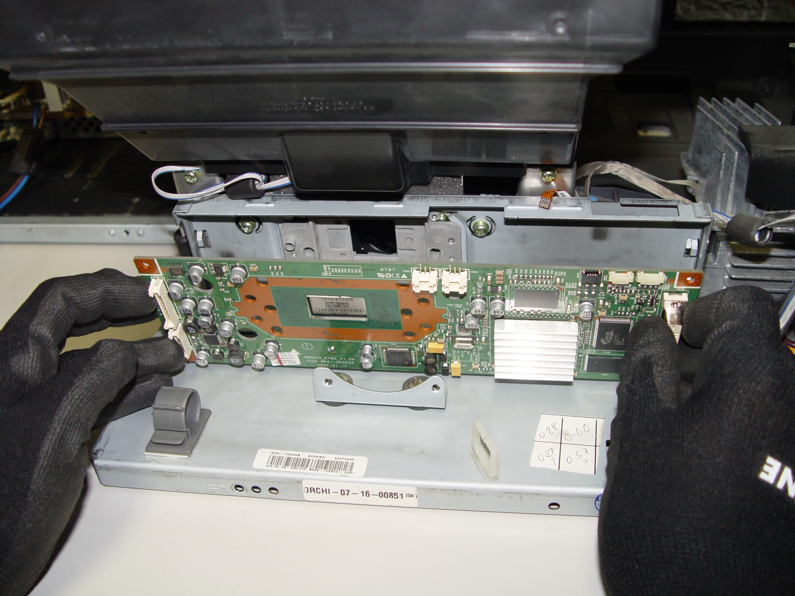
Step 13
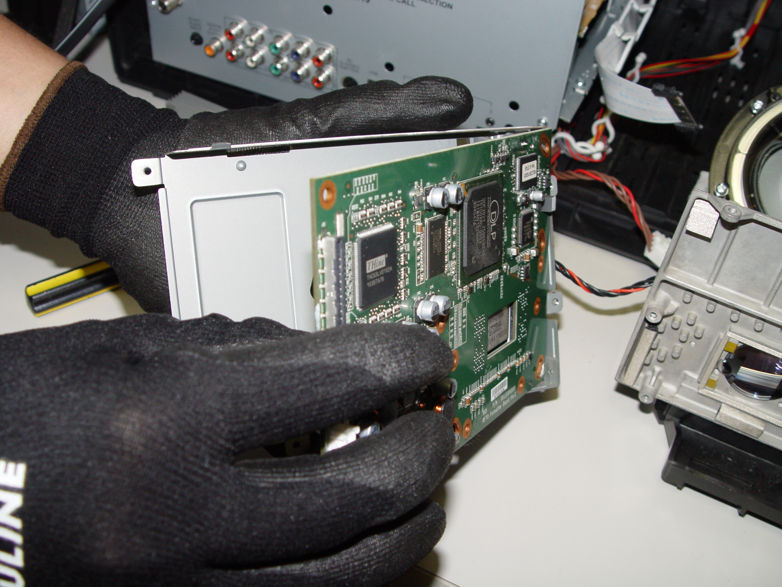
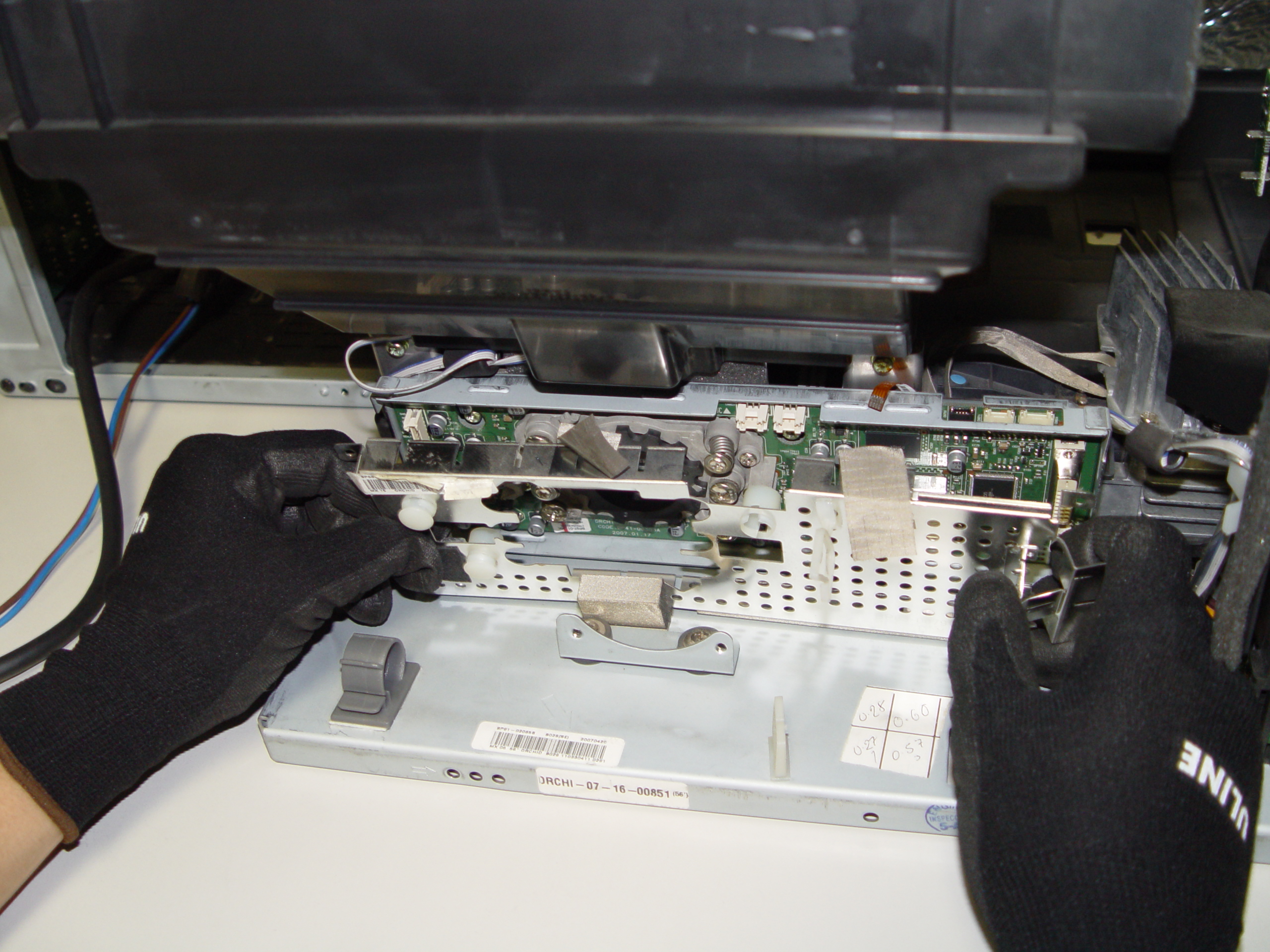
Step 13: Carefully pop the terminal out of its holder.
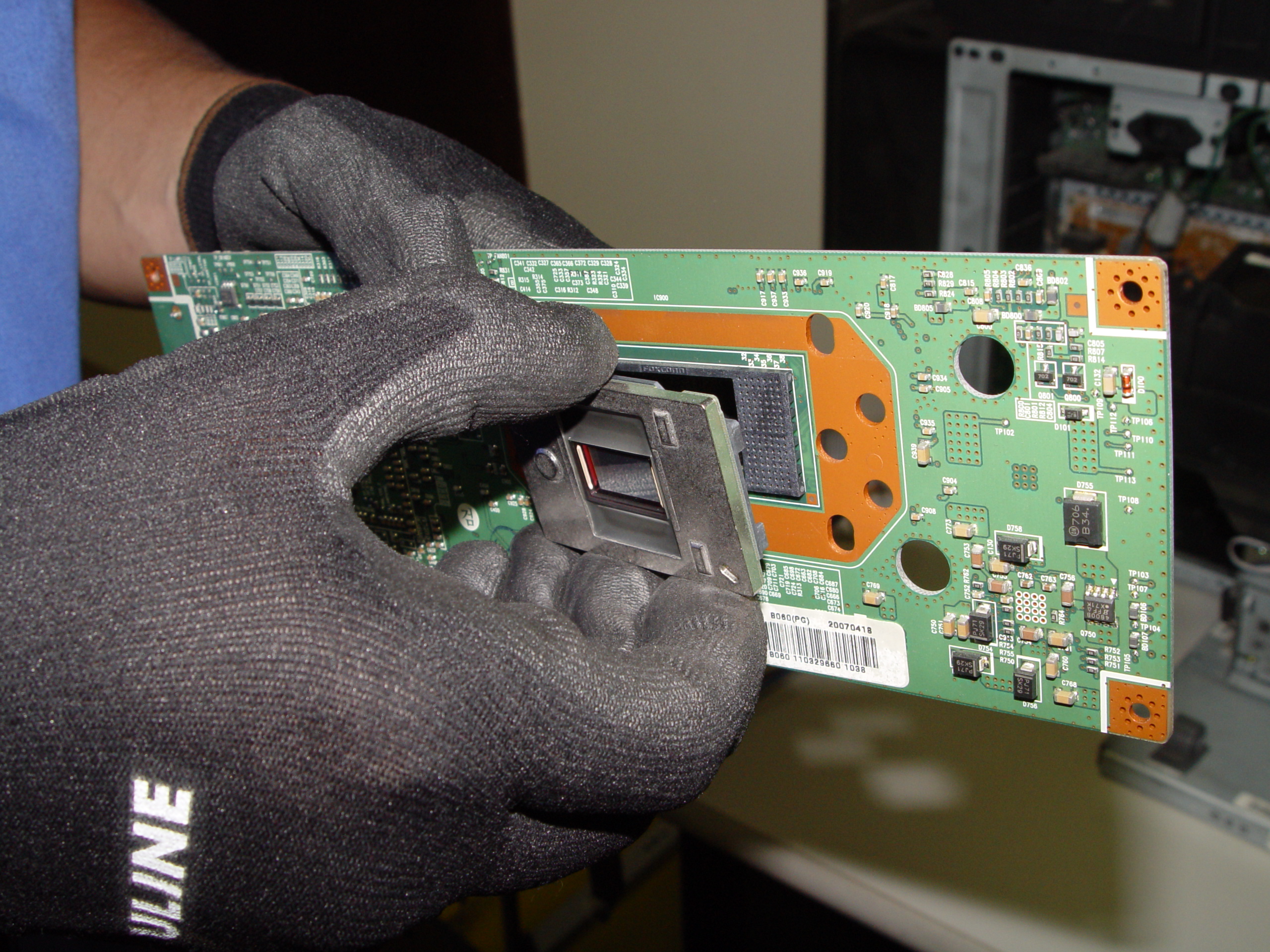
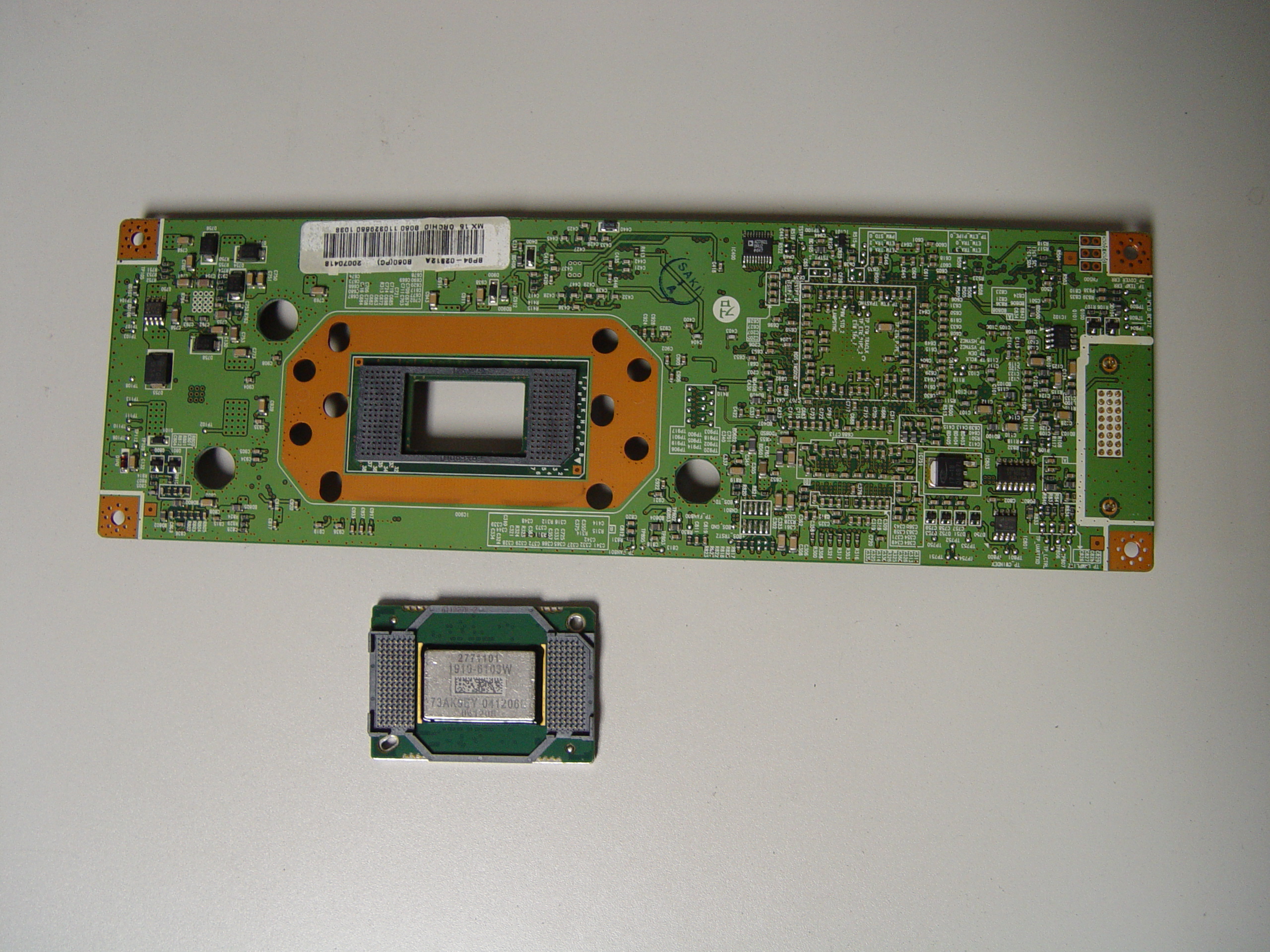
Step 14
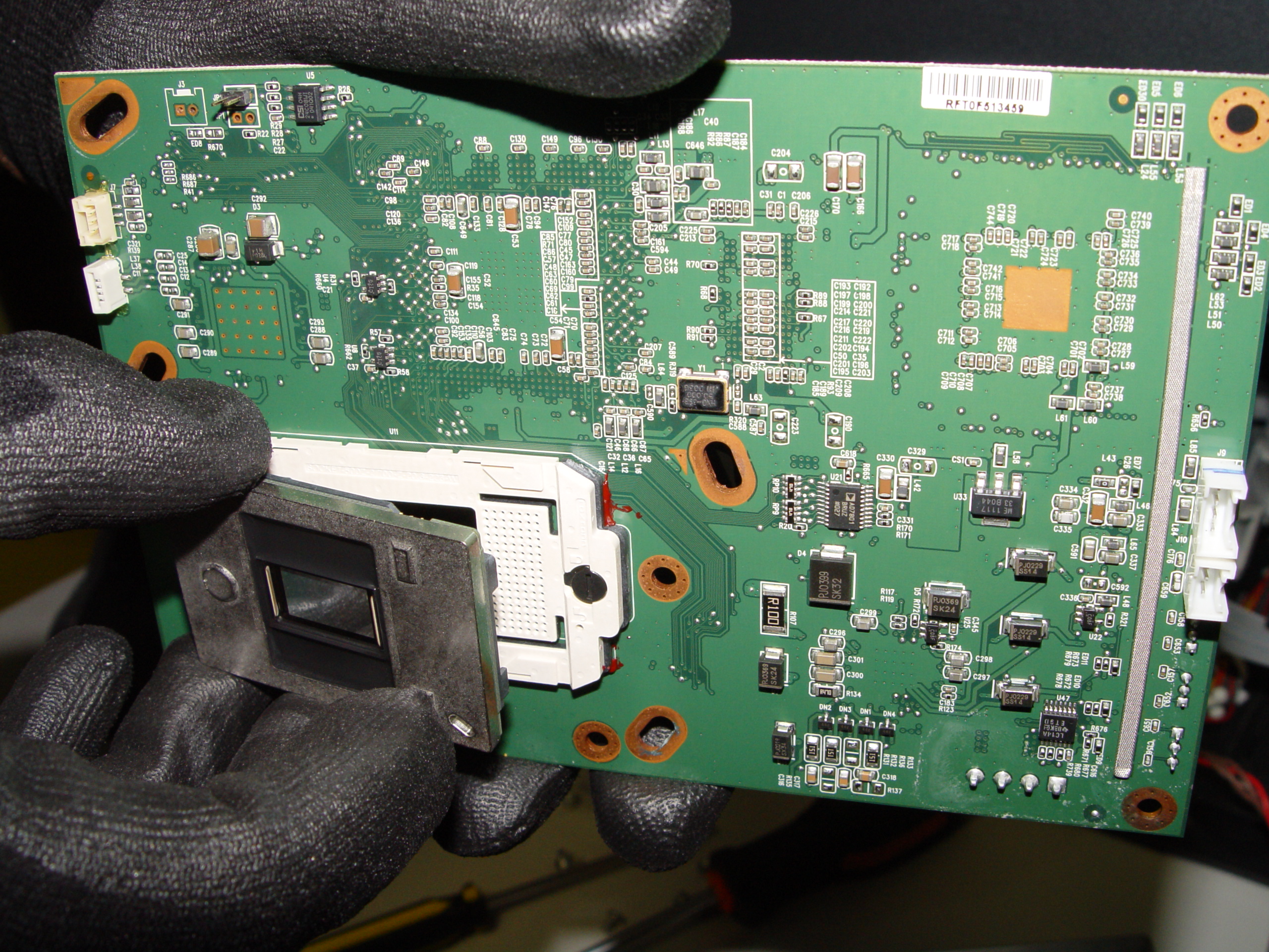
Step 14: Unlock the old DLP Chip from the terminal. You may need to loosen the screw on the side or use a flat edged screwdriver to pop it out.
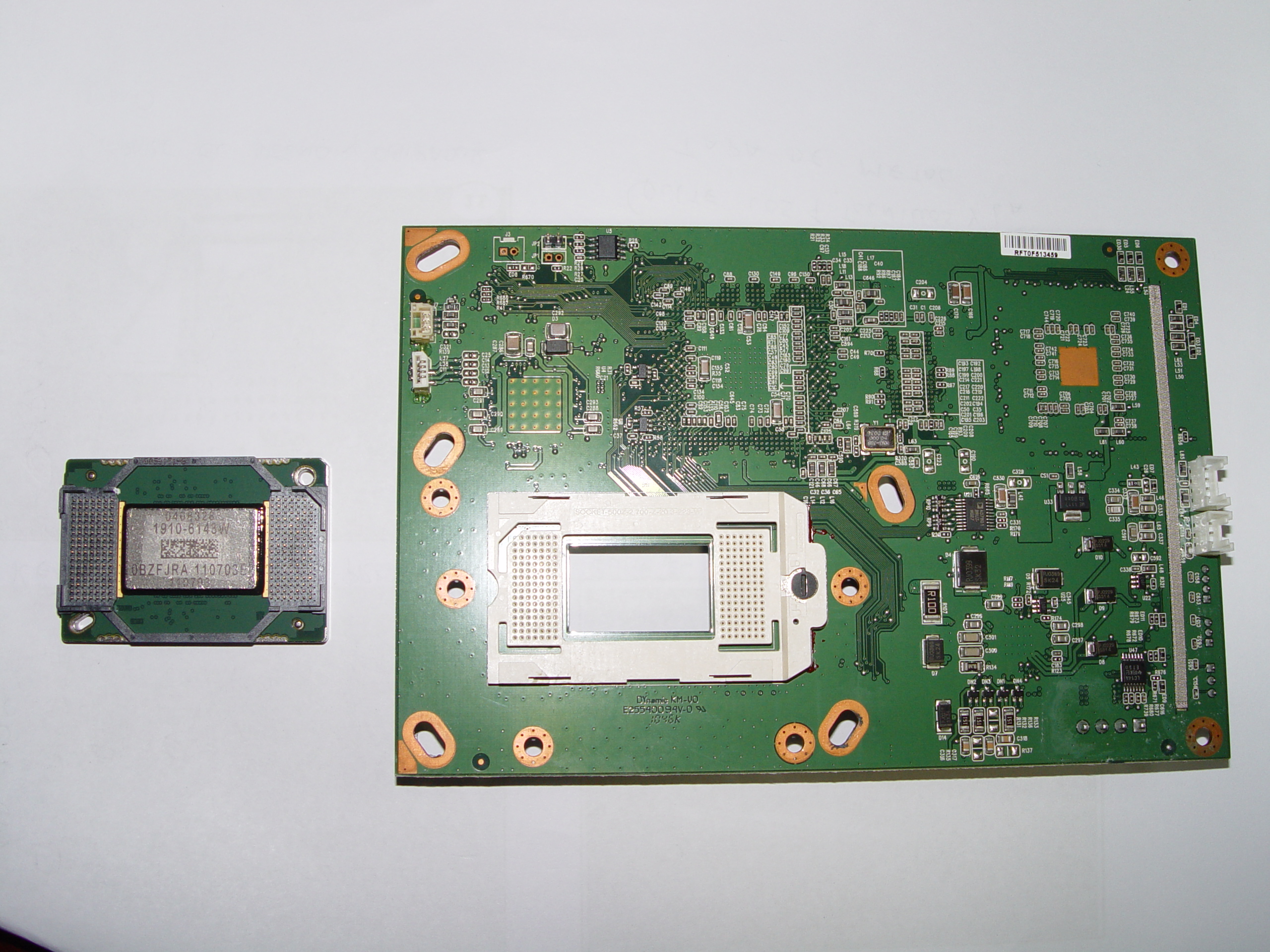
Step 15
Step 15: Place the new DLP chip into place. Handle the DMD DLP CHIP only by the edges because it is very sensitive to antistatic electricity.
Step 16
Step 16: Put the terminal back into its holder.
Step 17
Step 17: Tighten the 10 screws holding the terminal in place.
Step 18
Step 18: Tighten the 2 screws on terminal board’s cover.
Step 19
Step 19: Put the fan unit back on.
Step 20
Step 20: Tighten the 3 screws holding the cooling unit/fan to the terminal board.
Step 21
Step 21: Reconnect the cables connecting the color wheel.
Step 22
Step 22: Reconnect the cable between the terminal board and lamp.
Step 23
Step 23: Replace the color wheel protective cover and tighten the 3 screws.
Step 24
Step 24: Re-connect all the cables running from the terminal board and light engine.
Step 25
Step 25: Carefully place the light engine back inside the unit. Tighten the 3 holding the terminal board and light engine in place.
Step 26
Step 26: Put the back panel back onto the TV.
Step 27
Step 27: Tighten all the screws on the back panel. Enjoy your crisp, clear picture on your Mitsubishi WD-65736 RPTV.
Learn more about your Mitsubishi WD-65736 RPTV:
Find this new Mitsubishi/Toshiba 4719-001997 DLP Chip 1910-6143W on Amazon.


 Get rid of Samsung HLT7288WX/XAA white dots
 Get rid of white dots on the Samsung HLT5055WX/XAA screen
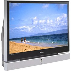 White dots on the Samsumg 50A650C1FXZA means the DLP chip needs replacing
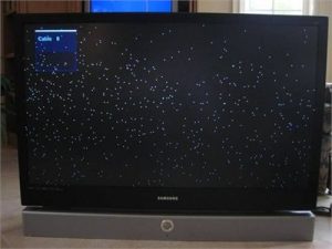 White dots on Samsung HL72A650C1FXZA screen can easily be repaired