We're now Screen and Projector! For updated content, visit ScreenAndProjector.com and follow @screenandproj on social media!

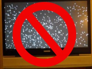
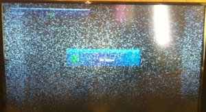
4719-001997 DLP Chip, Samsung HLT5687SX RPTVSamsung HLT5687SAX/XAA white dots on screen means it’s time for a new DLP Chip
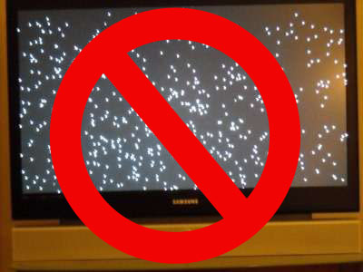
If white dots are ruining hour viewing pleasure on your Samsung HLT5687SAX/XAA the solution is to replace the 4719-001997 DLP CHip. We show you how to do this.

Note: These instructions can also be used for the following Samsung models: 

50A650C1FXZA, HLT5055WX/XAA , HLT5076SX/XAA, HLT5087SX/XAA, HLS5087WX/XAA, HL56A650C1FXZA, HLT5656WX/XAA, HLT5676SX/XAA, HLT5687SX/XAA, HLT5687SAX/XAA, HLT5689SX/XAA, HLT6156WX/XAA, HL61A650C1FXZA, HL61A750A1FXZA, HLT6156WX/XAA, HLT6176SX/XAA, HLT6187SAX/XAA, HLT6187SX/XAA, HLS6187WX/XAA, HLT6189SX/XAA, HL67A750A1FXZA, HLT6756WX/XAA, HL72A650C1FXZA, HLT7288WX/XAA

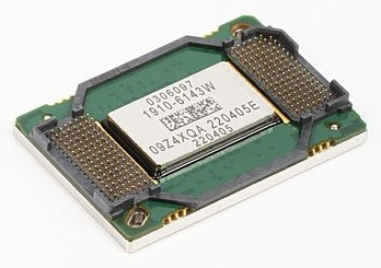
Find this New Mitsubishi/Toshiba 4719-001997 DLP Chip 1910-6143W on Amazon.

Equipment needed

      • Electric Philips screwdriver
      • needle nose pliers or a 5mm nut driver
      • antistatic gloves OR plastic gloves used with an antistatic wrist band
      • soft cloth or brush

Replacing the 4719-001997 DLP Chip
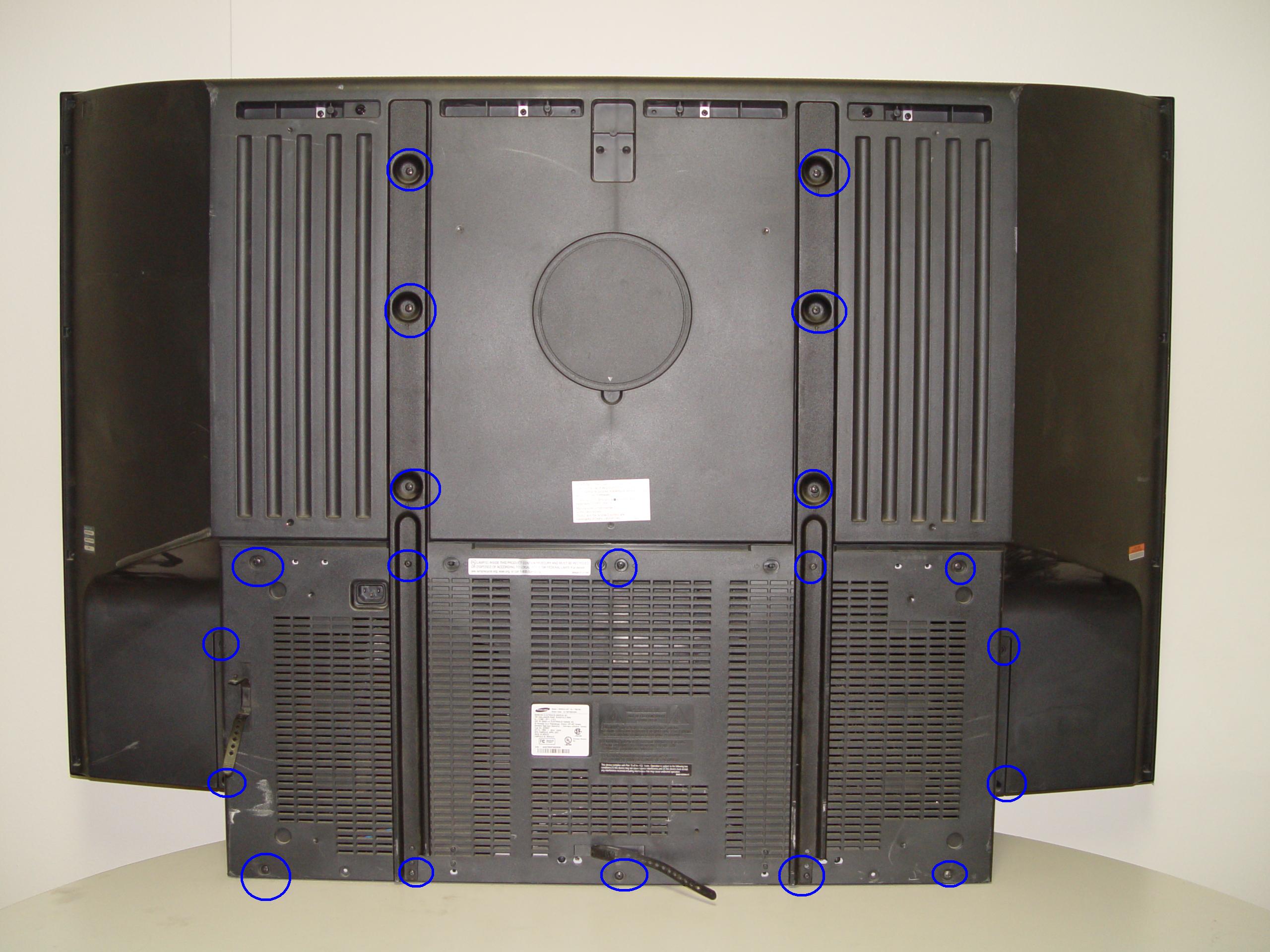
4719-001997 DLP Chip, Samsung HLT5687SAX/XAA RPTV

Step 1

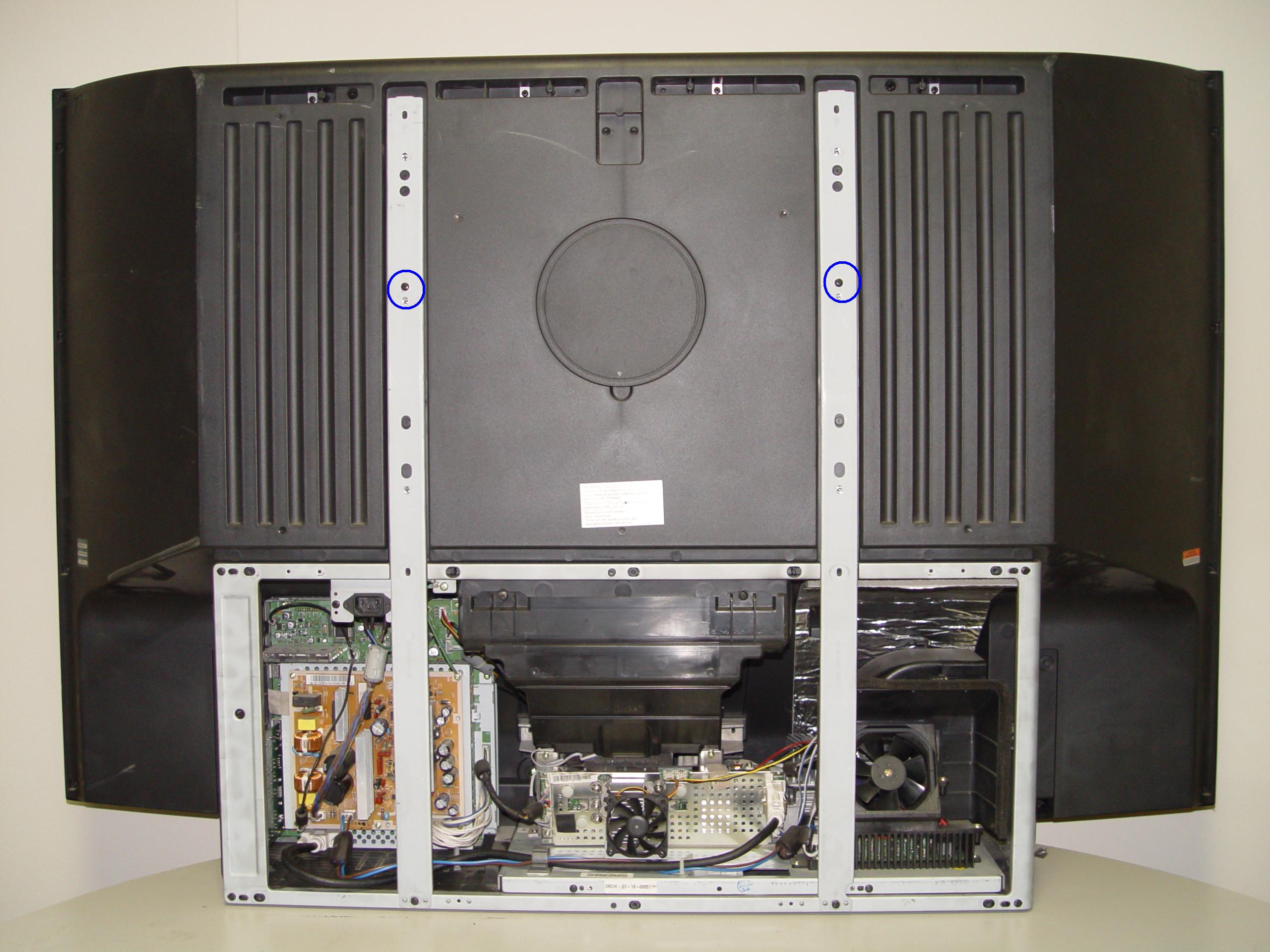
Step 1: Put on the plastic gloves. Loosen all the screws found on the back panel. Put the screws to one side and remove the back panel.
4719-001997 DLP Chip, Samsung HLT5687SAX/XAA RPTV

Step 2

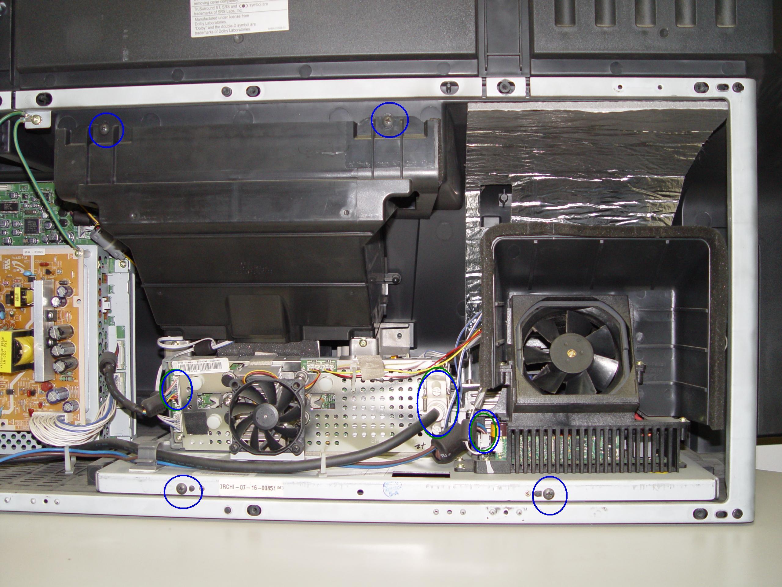
Step 2: Loosen the two screws holding the lamp bracket in place.
4719-001997 DLP Chip, Samsung HLT5687SAX/XAA RPTV

Step 3

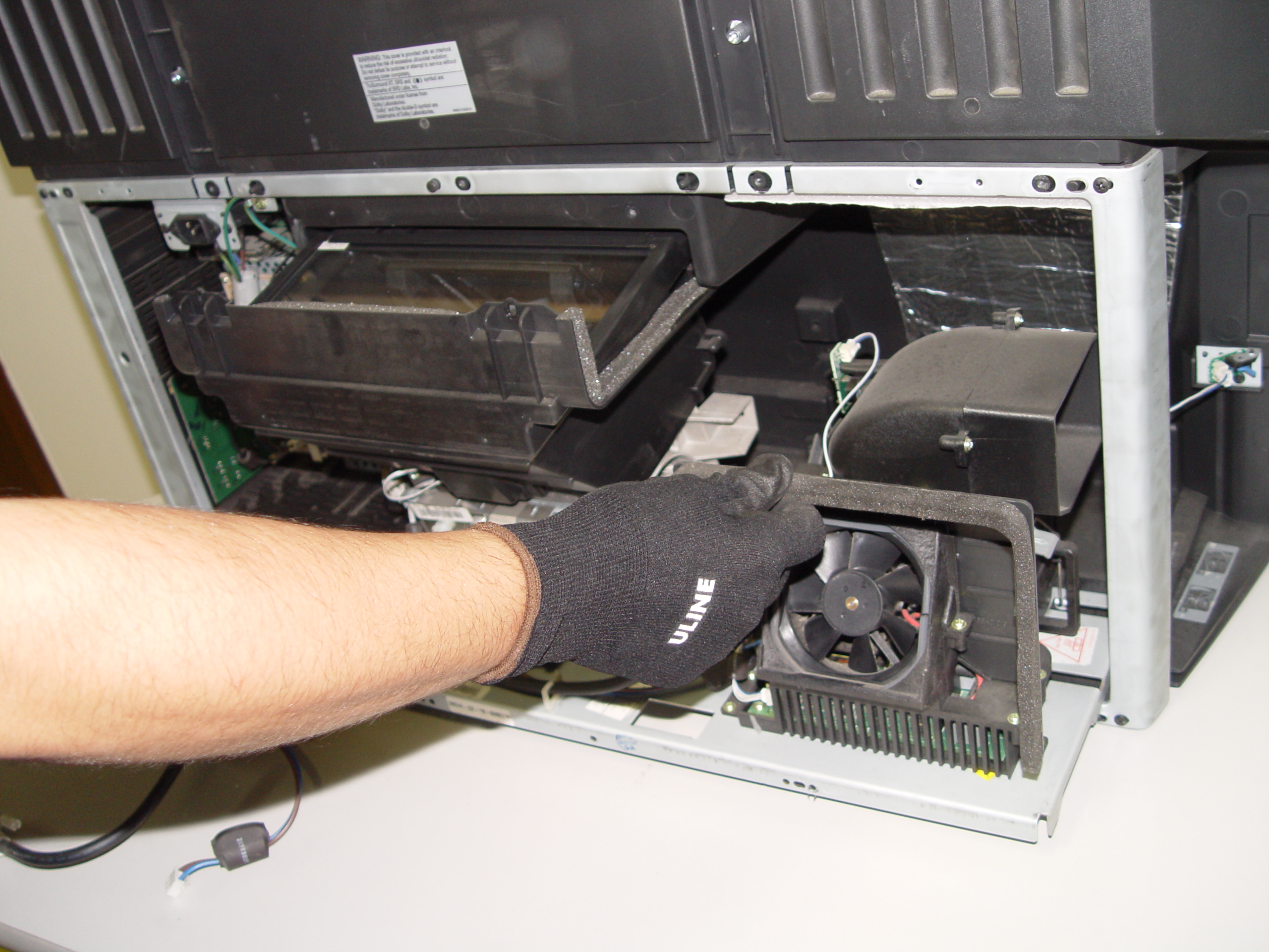
Step 3: Remove the 4 screws holding the lamp engine in place. Disconnect all the connectors. Important: don’t yank any cables.
4719-001997 DLP Chip, Samsung HLT5687SAX/XAA RPTV

Step 4

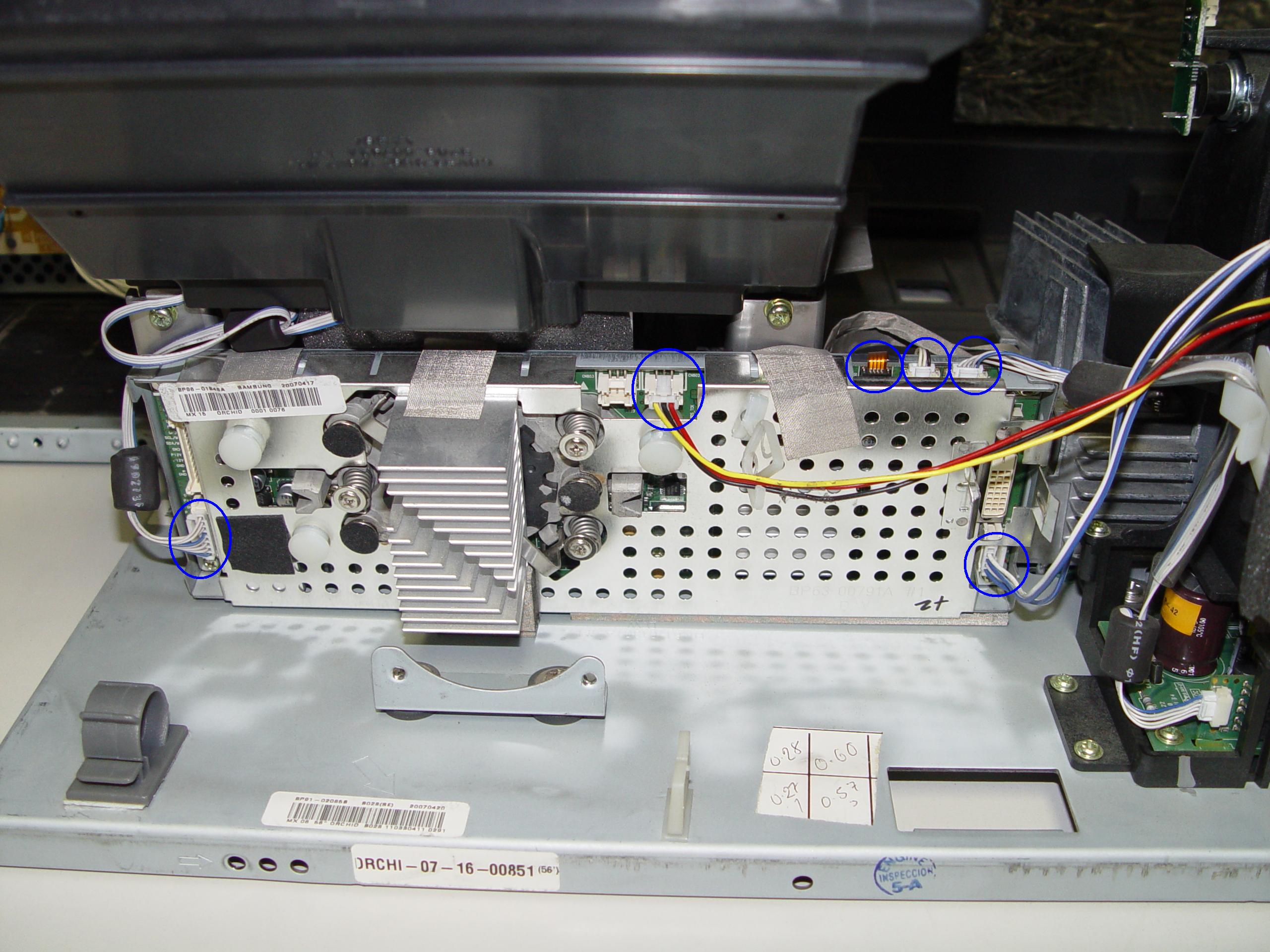
Step 4: Carefully remove light engine from the cabinet.
4719-001997 DLP Chip, Samsung HLT5687SAX/XAA RPTV

Step 5

Step 5: Remove the 2 screws holding the color wheel protective cover in it place. Avoid touching any of the optical components as this can affect the quality of your picture.
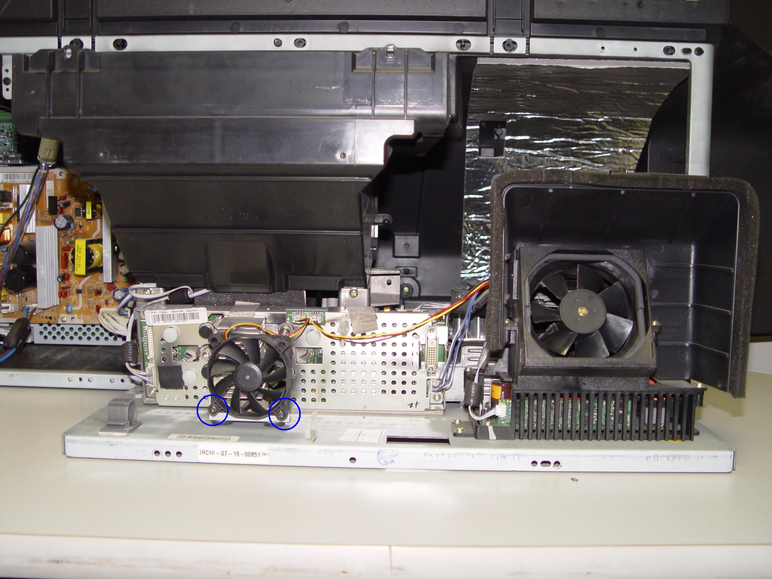
4719-001997 DLP Chip, Samsung HLT5687SAX/XAA RPTV

Step 6

Step 6: Carefully disconnect the cables between the terminal board and lamp.
4719-001997 DLP Chip, Samsung HLT5687SAX/XAA RPTV

Step 7

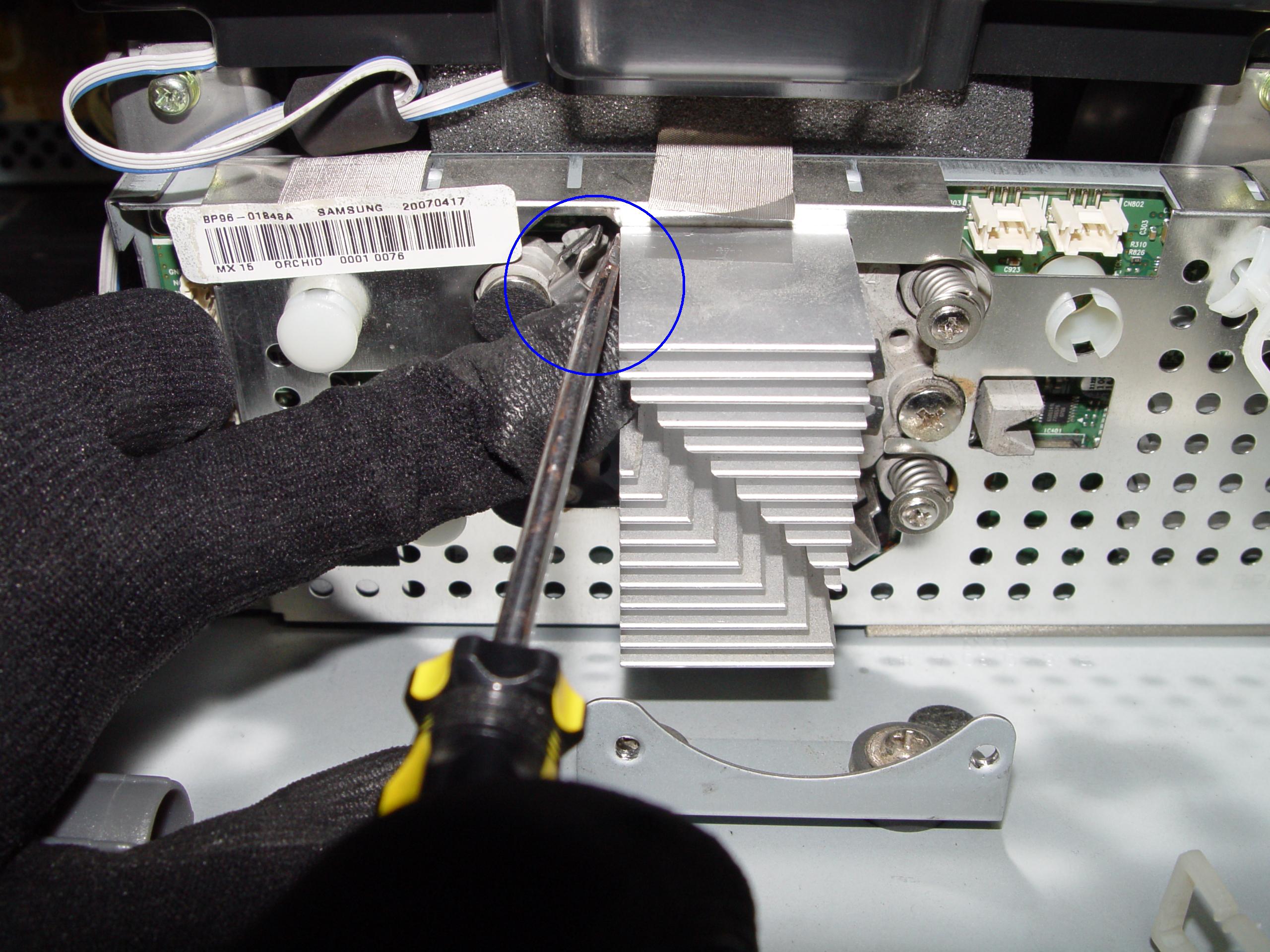
Step 7: Disconnect the clip connecting the cooling unit.
4719-001997 DLP Chip, Samsung HLT5687SAX/XAA RPTV

Step 8

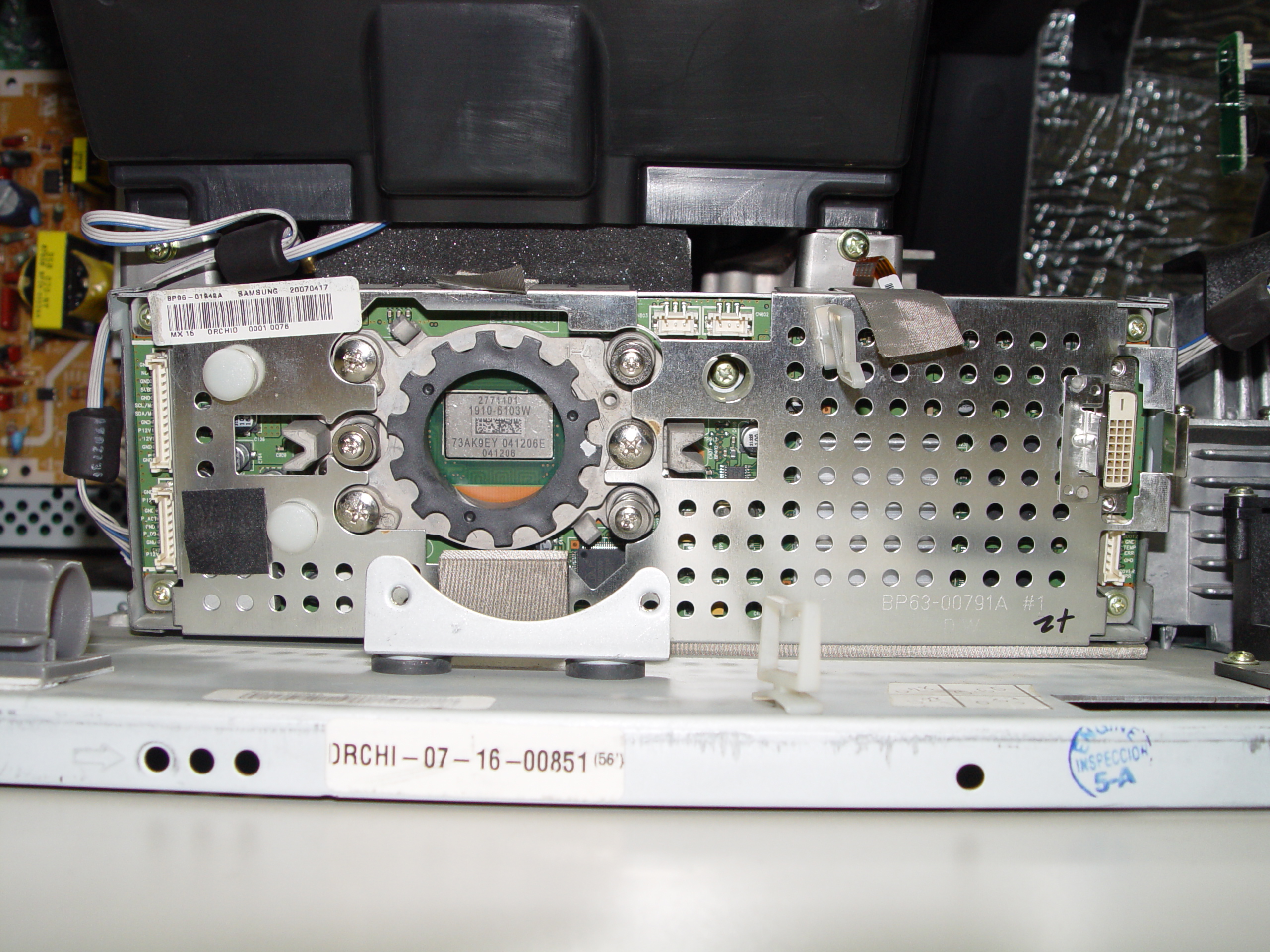
Step 8: Remove the cooling unit and terminal board.
4719-001997 DLP Chip, Samsung HLT5687SAX/XAA RPTV

Step 9

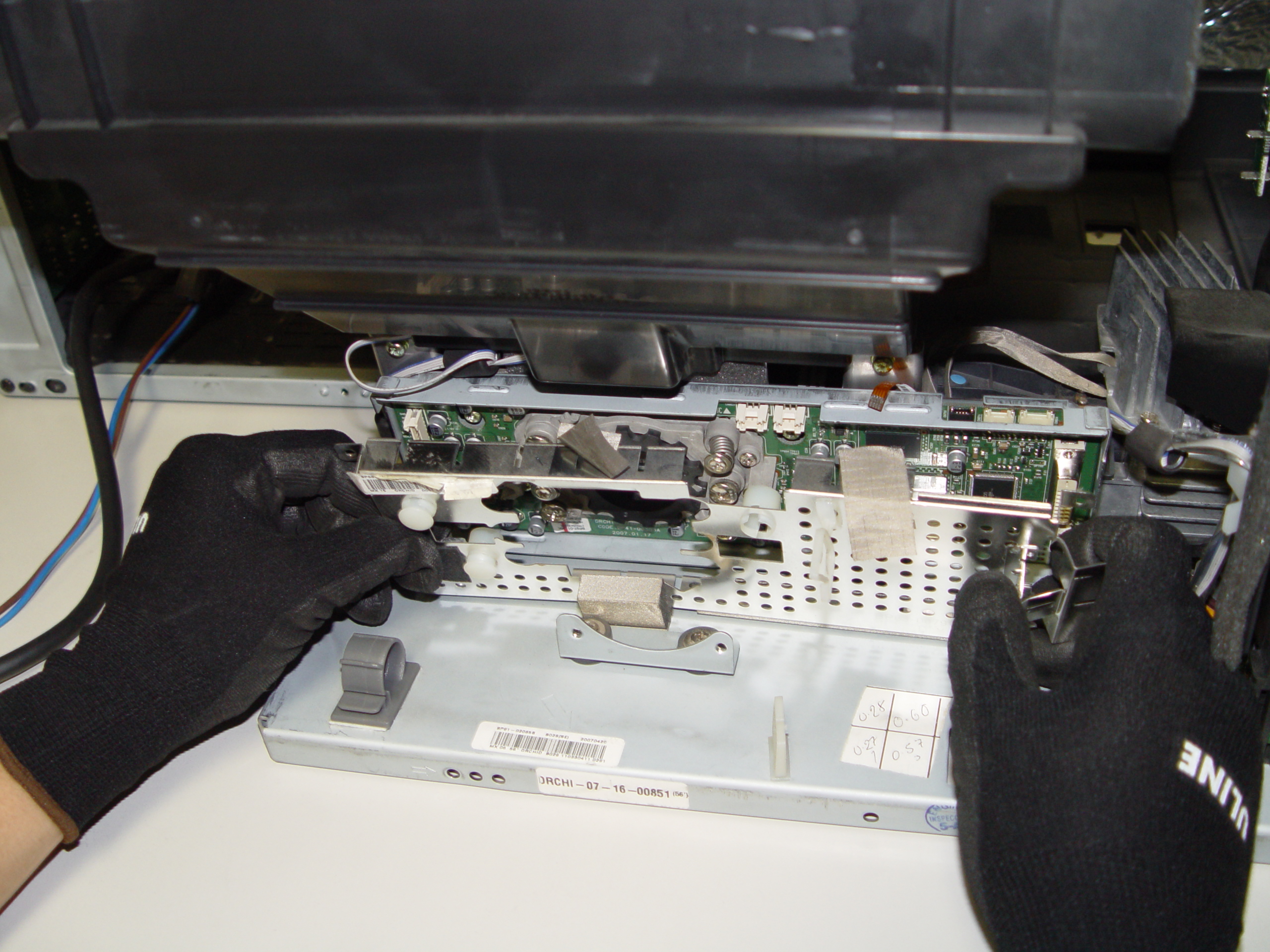
Step 9: Remove the terminal board.
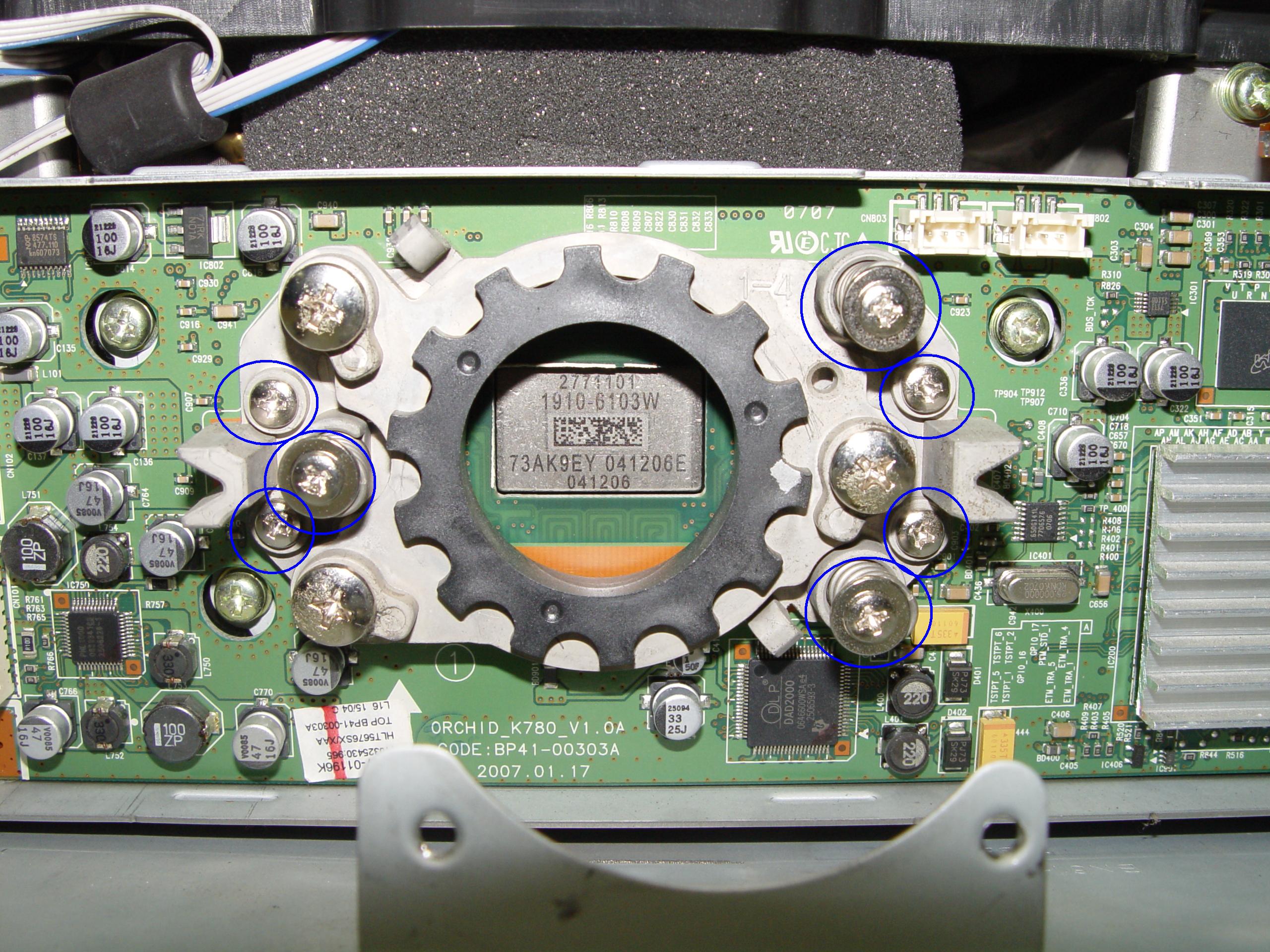
4719-001997 DLP Chip, Samsung HLT5687SAX/XAA RPTV

Step 10

Step 10: Loosen the 7 screws holding the terminal cover in place. (Good time to dust this section).
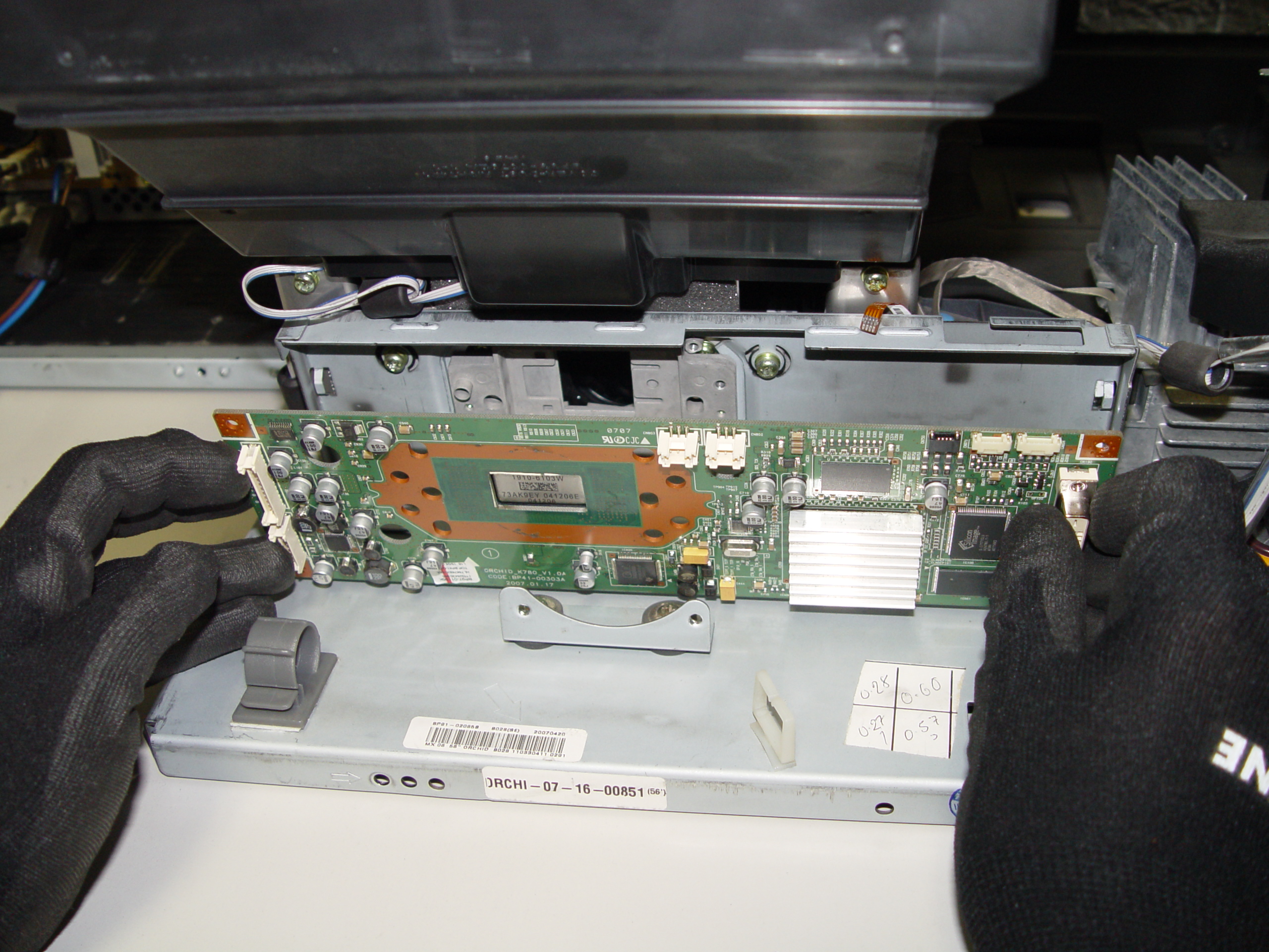
4719-001997 DLP Chip, Samsung HLT5687SAX/XAA RPTV

Step 11

Step 11: Carefully pop the terminal out of its holder.
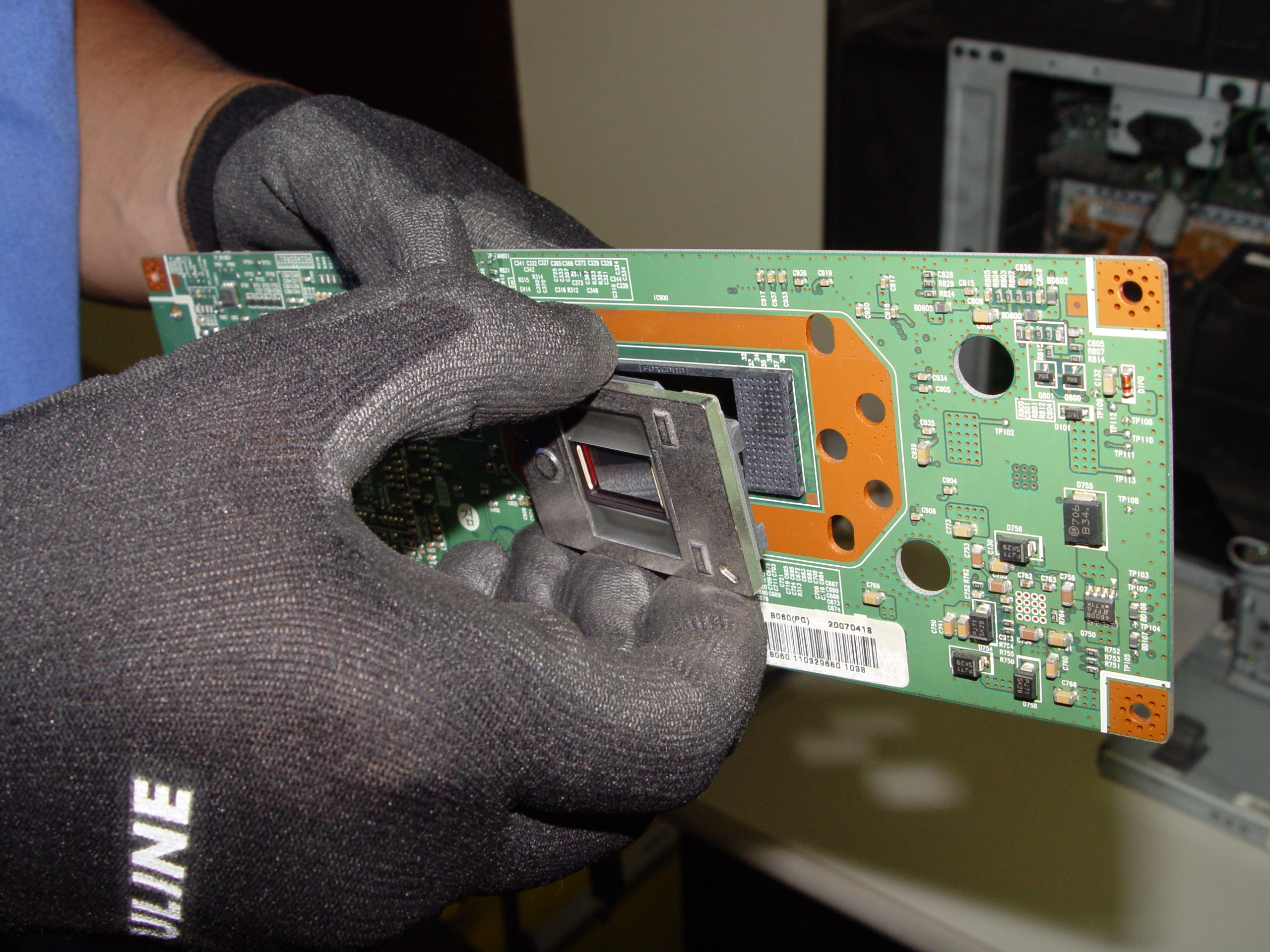
4719-001997 DLP Chip, Samsung HLT5687SAX/XAA RPTV

Step 12

Step 12: Unlock the old DLP Chip from the terminal. You may need to use a flat edged screwdriver to pop it out.
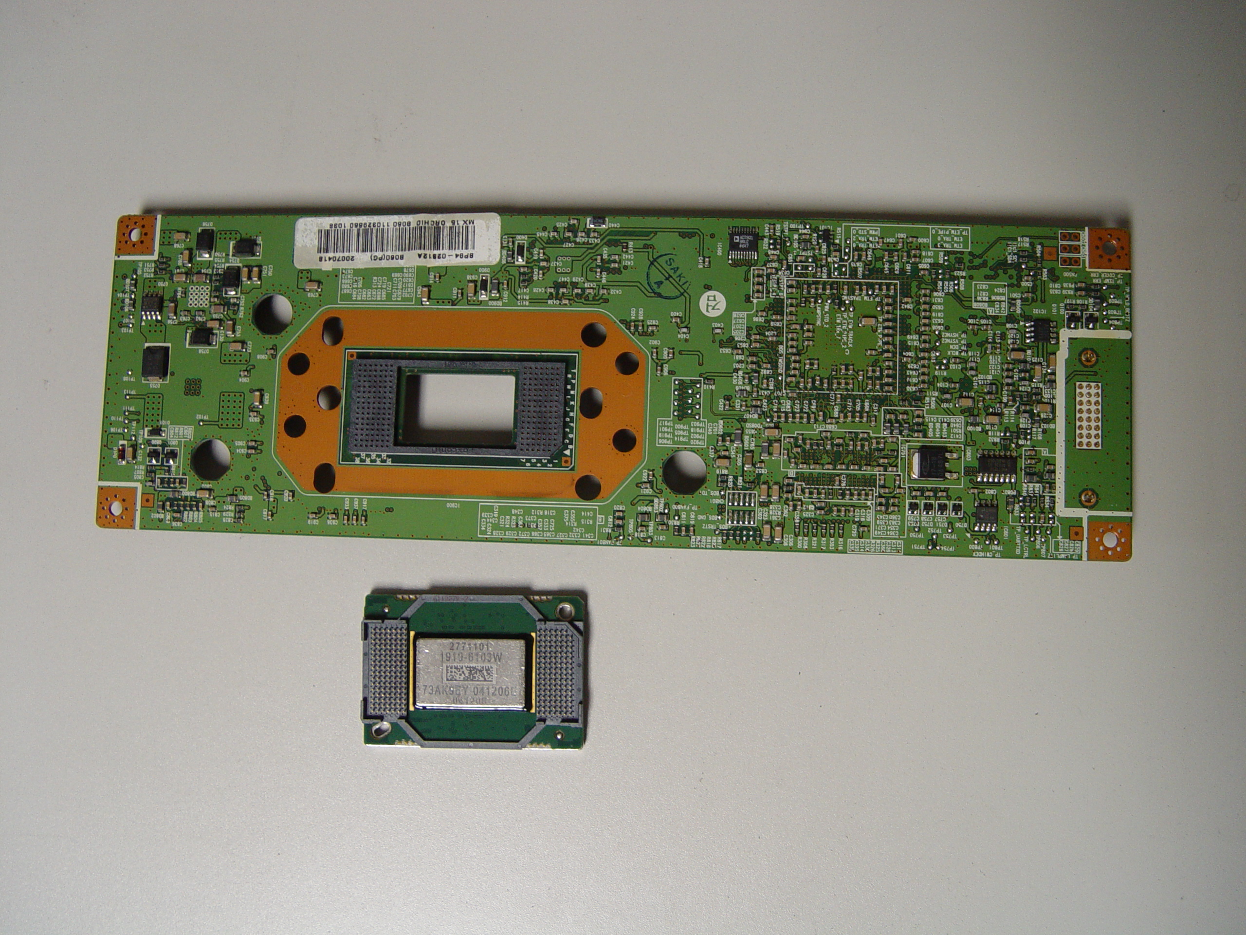
4719-001997 DLP Chip, Samsung HLT5687SAX/XAA RPTV

Step 13

Step 13: Place the new DLP chip into place. Handle the DMD DLP CHIP only by the edges because it is very sensitive to static electricity.

4719-001997 DLP Chip, Samsung HLT5687SAX/XAA RPTV

Step 14

Step 14: Put the terminal back into its holder.

4719-001997 DLP Chip, Samsung HLT5687SAX/XAA RPTV

Step 15

Step 15: Tighten the 7 screws holding the terminal in place.
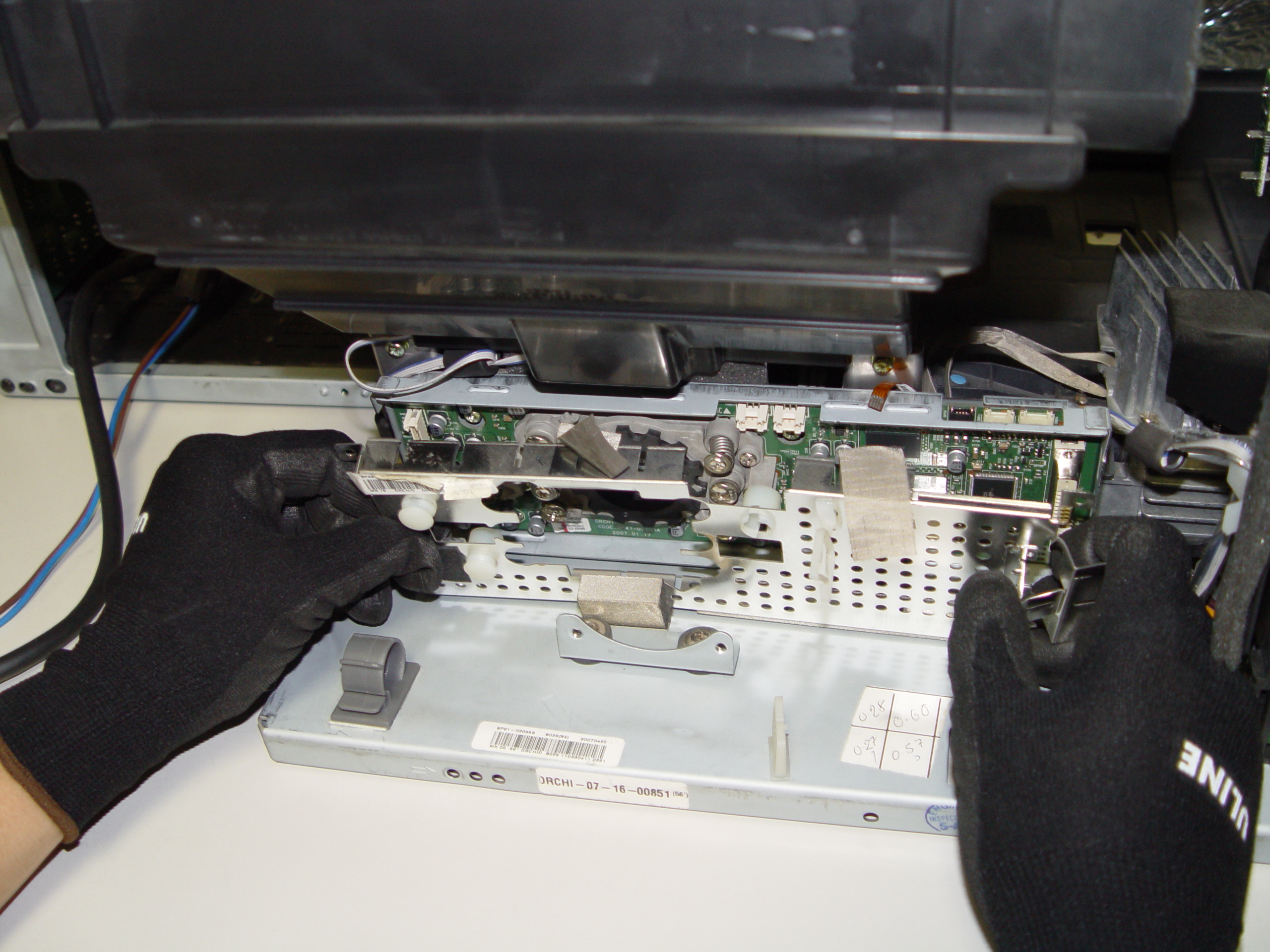
 

4719-001997 DLP Chip, Samsung HLT5687SAX/XAA RPTV

Step 16

Step 16: Replace the terminal board’s cover.
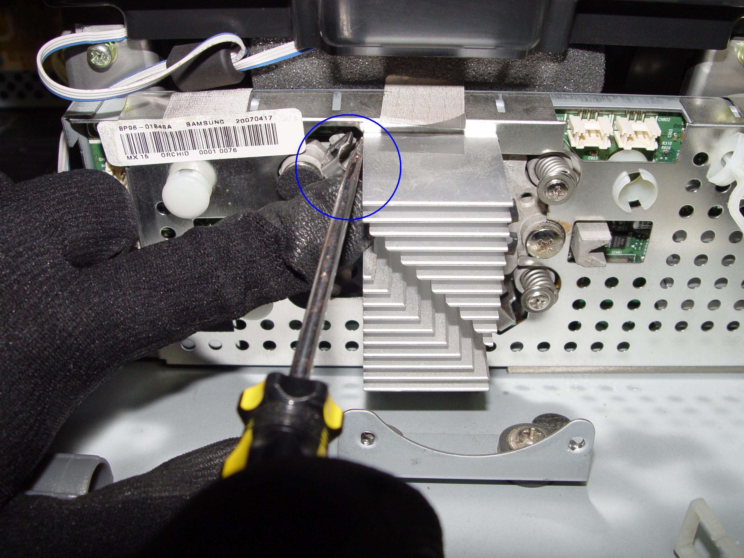
4719-001997 DLP Chip, Samsung HLT5687SAX/XAA RPTV

Step 17

Step 17: Reconnect the clip holding the cooling unit.
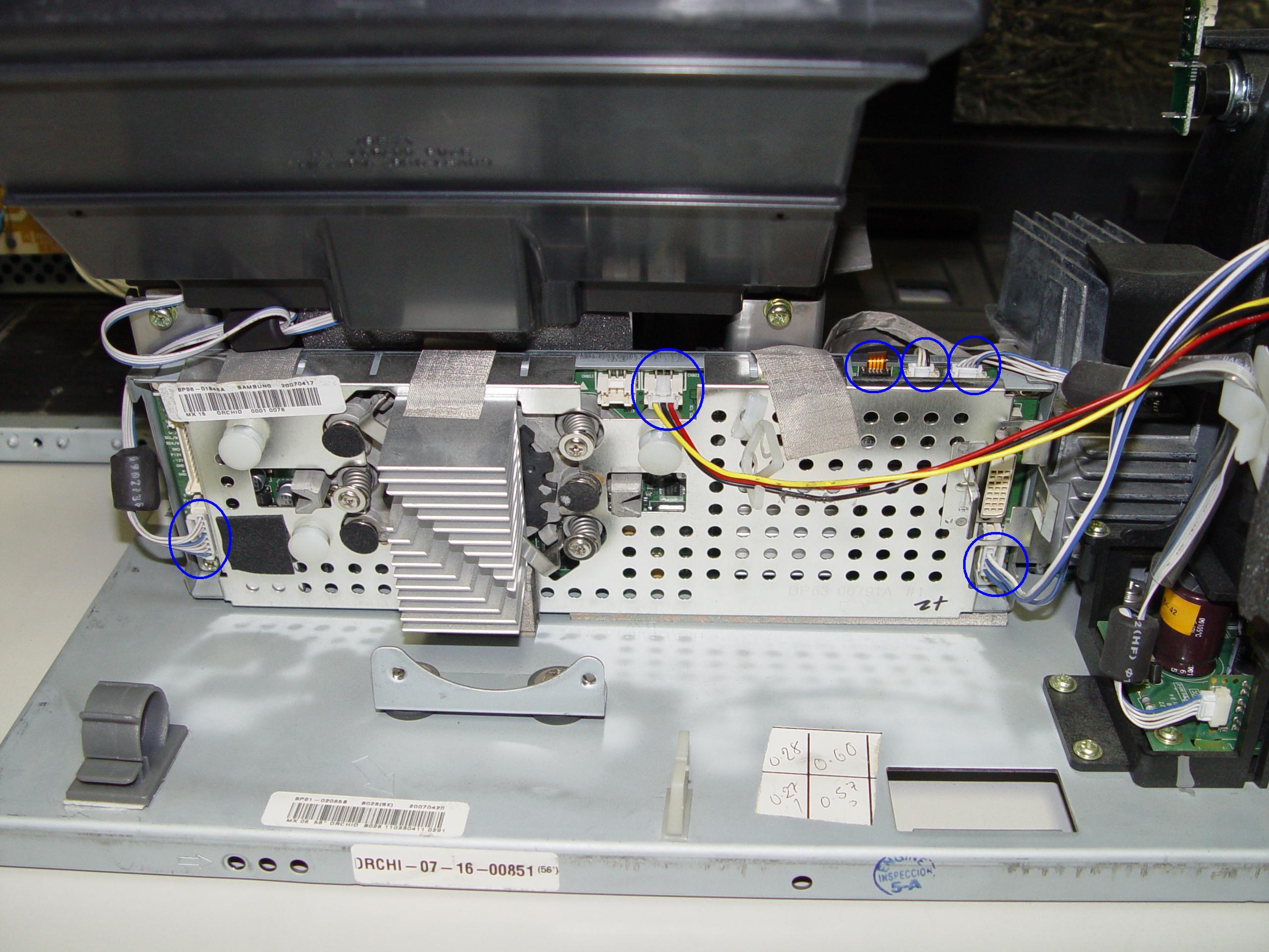
4719-001997 DLP Chip, Samsung HLT5687SAX/XAA RPTV

Step 18

Step 18: Re-connect the cables between the terminal board and lamp.
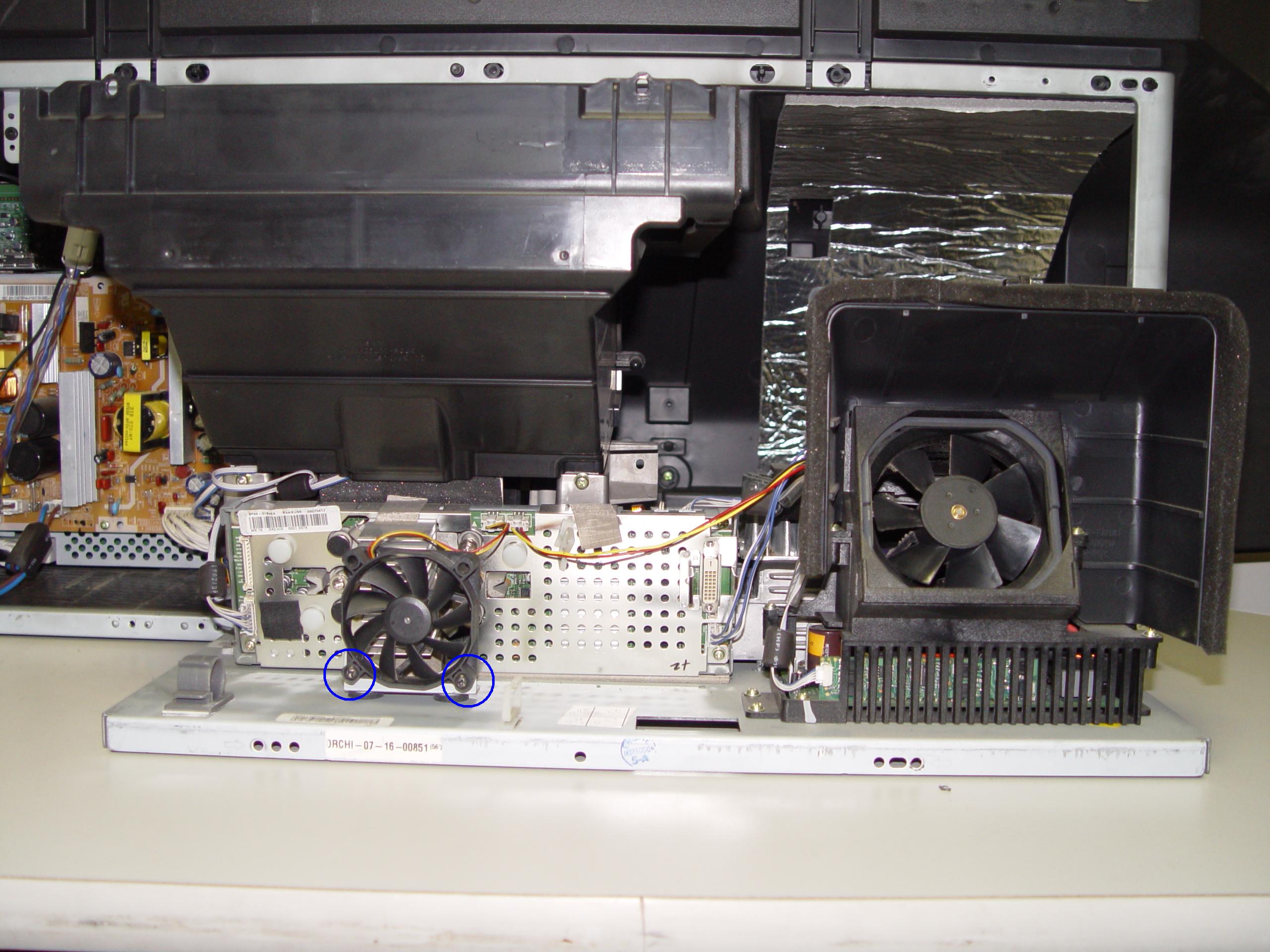
4719-001997 DLP Chip, Samsung HLT5687SAX/XAA RPTV

Step 19

Step 19: Tighten the 2 screws holding the color wheel protective cover in it place. Avoid touching any of the optical components as this can affect the quality of your picture.
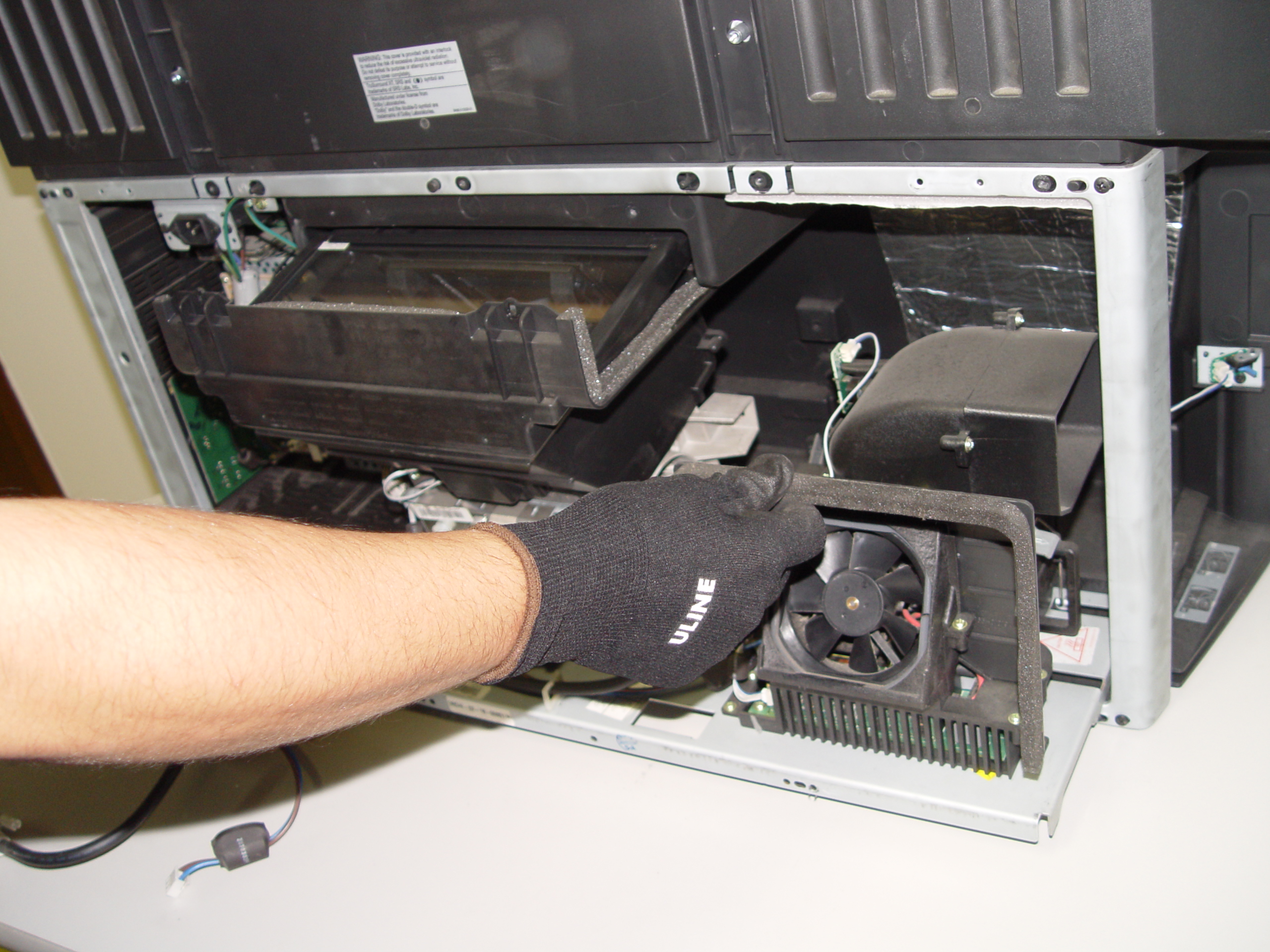
4719-001997 DLP Chip, Samsung HLT5687SAX/XAA RPTV

Step 20

Step 20: Carefully replace the light engine back into the cabinet.
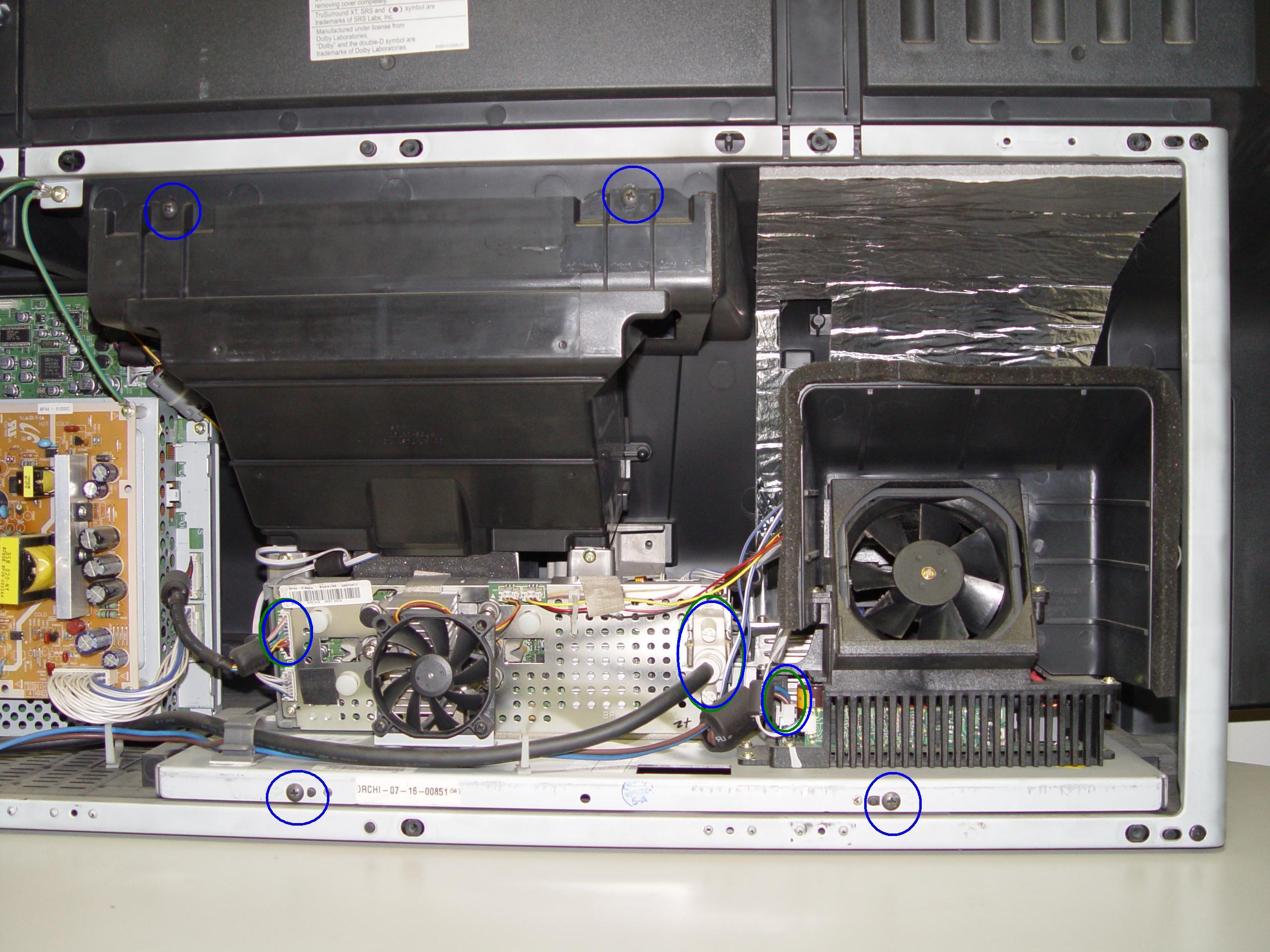
4719-001997 DLP Chip, Samsung HLT5687SAX/XAA RPTV

Step 21

Step 21: Replace and tighten the 4 screws holding the lamp engine in place. Re-connect all the connectors.
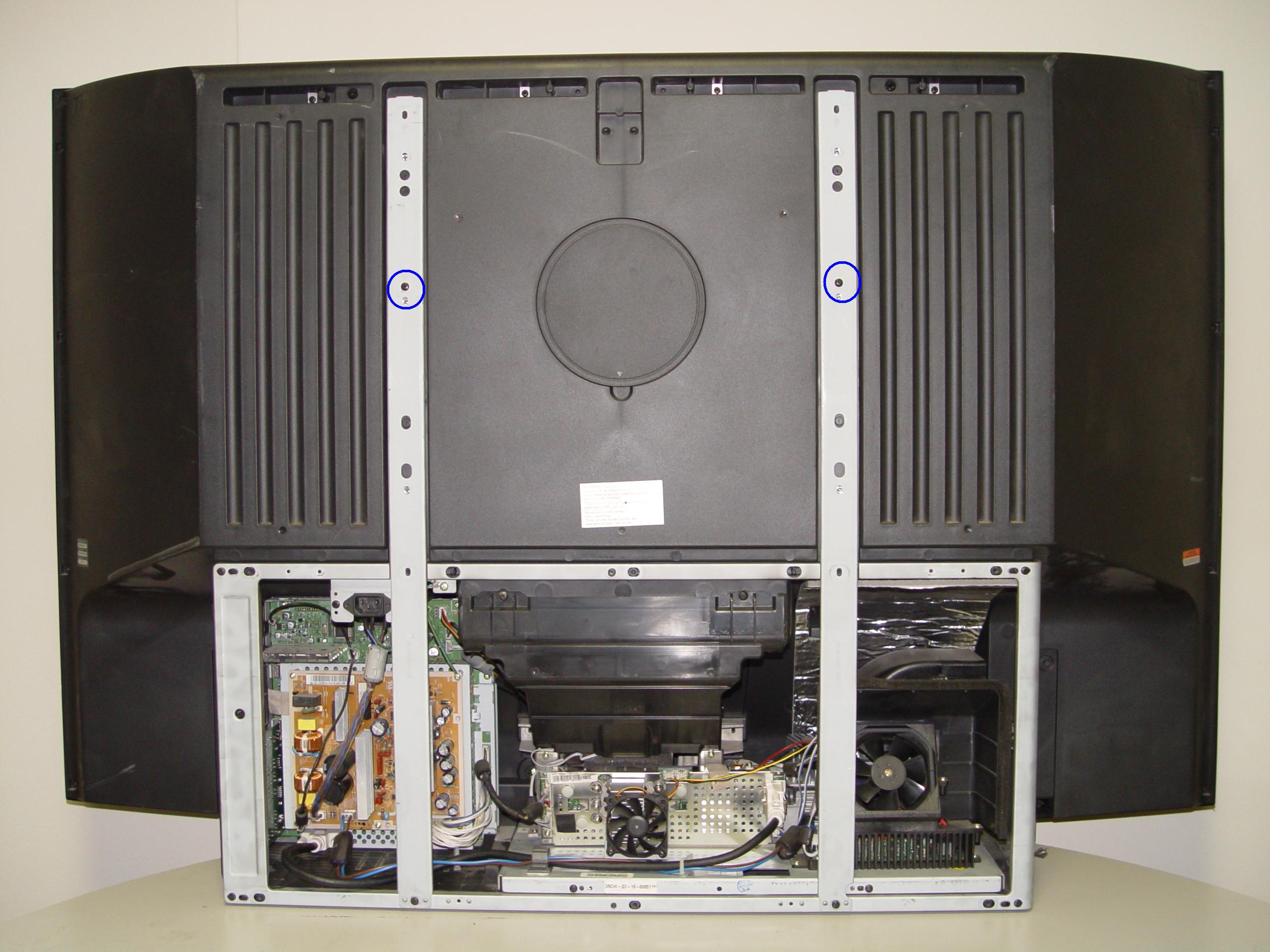
4719-001997 DLP Chip, Samsung HLT5687SAX/XAA RPTV

Step 22

Step 22: Put the light engine back into the RPTV. Tighten both screws that keep the back bracket in place.

4719-001997 DLP Chip, Samsung HLT5687SAX/XAA RPTV

Step 23

Step 23: Put the back panel onto the TV. Put the screws back into place and tighten them. Enjoy the crisp, clear picture on your Samsung HLT5687SAX/XAA RPTV.

Learn more about your Samsung HLT5687SAX/XAA RPTV:

Shop on Amazon for this chip.

Tagged with: , , ,

new 4719-001997 DLP Chip in the Samsung HLT5087SX RPTV

Seeing white dots on your Samsung HL67A750A1FXZA? Time to replace the DLP Chip

Replace your 4719-001997 DLP Chip for under $300 and get rid of those white dots.

Note: These instructions can be used for the following Samsung models:

50A650C1FXZA, HLT5055WX/XAA , HLT5076SX/XAA, HLT5087SX/XAA, HLS5087WX/XAA, HL56A650C1FXZA, HLT5656WX/XAA, HLT5676SX/XAA, HLT5687SX/XAA, HLT5687SAX/XAA, HLT5689SX/XAA, HLT6156WX/XAA, HL61A650C1FXZA, HL61A750A1FXZA, HLT6156WX/XAA, HLT6176SX/XAA, HLT6187SAX/XAA, HLT6187SX/XAA, HLS6187WX/XAA, HLT6189SX/XAA, HL67A750A1FXZA, HLT6756WX/XAA, HL72A650C1FXZA, HLT7288WX/XAA

Find this New Mitsubishi/Toshiba 4719-001997 DLP Chip 1910-6143W on Amazon.

 Equipment needed

    • Electric Philips screwdriver
    • needle nose pliers or a 5mm nut driver
    • antistatic gloves OR plastic gloves used with an antistatic wrist band
    • soft cloth or brush

Replacing the 4719-001997 DLP Chip

4719-001997 DLP Chip, Samsung Stop Samsung HL67A750A1FXZA RPTV

Step 1

Step 1: Put on the plastic gloves. Loosen all the screws found on the back panel. Put the screws to one side and remove the back panel.

4719-001997 DLP Chip, Samsung HL67A750A1FXZA RPTV

Step 2

Step 2: Loosen the two screws holding the lamp bracket in place.

4719-001997 DLP Chip, Samsung HL67A750A1FXZA RPTV

Step 3

Step 3: Remove the 4 screws holding the lamp engine in place. Disconnect all the connectors. Important: don’t yank any cables.

4719-001997 DLP Chip, Samsung HL67A750A1FXZA RPTV

Step 4

Step 4: Carefully remove light engine from the cabinet.

4719-001997 DLP Chip, Samsung HL67A750A1FXZA RPTV

Step 5

Step 5: Remove the 2 screws holding the color wheel protective cover in it place. Avoid touching any of the optical components as this can affect the quality of your picture.

4719-001997 DLP Chip, Samsung HL67A750A1FXZA RPTV

Step 6

Step 6: Carefully disconnect the cables between the terminal board and lamp.

4719-001997 DLP Chip, Samsung HL67A750A1FXZA RPTV

Step 7

Step 7: Disconnect the clip connecting the cooling unit.

4719-001997 DLP Chip, Samsung HL67A750A1FXZA RPTV

Step 8

Step 8: Remove the cooling unit and terminal board.

4719-001997 DLP Chip, Samsung HL67A750A1FXZA RPTV

Step 9

Step 9: Remove the terminal board.

4719-001997 DLP Chip, Samsung HL67A750A1FXZA RPTV

Step 10

Step 10: Loosen the 7 screws holding the terminal cover in place. (Good time to dust this section).

4719-001997 DLP Chip, Samsung HLT5087SX RPTV

Step 11

Step 11: Carefully pop the terminal out of its holder.

4719-001997 DLP Chip, Samsung HL67A750A1FXZA RPTV

Step 12

Step 12: Unlock the old DLP Chip from the terminal. You may need to use a flat edged screwdriver to pop it out.

4719-001997 DLP Chip, Samsung HL67A750A1FXZA RPTV

Step 13

Step 13: Place the new DLP chip into place. Handle the DMD DLP CHIP only by the edges because it is very sensitive to static electricity.

4719-001997 DLP Chip, Samsung HL67A750A1FXZA RPYV

Step 14

Step 14: Put the terminal back into its holder.

4719-001997 DLP Chip, Samsung HL67A750A1FXZA RPTV

Step 15

Step 15: Tighten the 7 screws holding the terminal in place.

4719-001997 DLP Chip, Samsung HL67A750A1FXZA RPTV

Step 16

Step 16: Replace the terminal board’s cover.

4719-001997 DLP Chip, Samsung HL67A750A1FXZA RPTV

Step 17

Step 17: Reconnect the clip holding the cooling unit.

4719-001997 DLP Chip, Samsung HL67A750A1FXZA RPTV

Step 18

Step 18: Re-connect the cables between the terminal board and lamp.

4719-001997 DLP Chip, Samsung HL67A750A1FXZA RPTV

Step 19

Step 19: Tighten the 2 screws holding the color wheel protective cover in it place. Avoid touching any of the optical components as this can affect the quality of your picture.

4719-001997 DLP Chip, Samsung HL67A750A1FXZA RPTV

Step 20

Step 20: Carefully replace the light engine back into the cabinet.

4719-001997 DLP Chip, Samsung HL67A750A1FXZA RPTV

Step 21

Step 21: Replace and tighten the 4 screws holding the lamp engine in place. Re-connect all the connectors.

4719-001997 DLP Chip, Samsung HL67A750A1FXZA RPTV

Step 22

Step 22: Put the light engine back into the RPTV. Tighten both screws that keep the back bracket in place.

4719-001997 DLP Chip, Samsung HL67A750A1FXZA RPTV

Step 23

Step 23: Put the back panel back onto the TV. Put the screws back into place and tighten. Enjoy the crisp, clear picture on your Samsung HL67A750A1FXZA RPTV.

Learn more about your Samsung HL67A750A1FXZA RPTV:

Shop on Amazon for this chip.

Tagged with: , , ,

4719-001997 DLP Chip, Samsung HLT5687SX RPTVGet rid of Samsung HLT7288WX/XAA white dots

White dots on your Samsung HLT7288WX/XAA screen  can be eliminated by replacing the 4719-001997 DLP chip. Follow the step by step guide below to replace this chip.

Note: These instructions can also be used for the following Samsung models: 

50A650C1FXZA, HLT5055WX/XAA , HLT5076SX/XAA, HLT5087SX/XAA, HLS5087WX/XAA, HL56A650C1FXZA, HLT5656WX/XAA, HLT5676SX/XAA, HLT5687SX/XAA, HLT5687SAX/XAA, HLT5689SX/XAA, HLT6156WX/XAA, HL61A650C1FXZA, HL61A750A1FXZA, HLT6156WX/XAA, HLT6176SX/XAA, HLT6187SAX/XAA, HLT6187SX/XAA, HLS6187WX/XAA, HLT6189SX/XAA, HL67A750A1FXZA, HLT6756WX/XAA, HL72A650C1FXZA, HLT7288WX/XAA

Find this New Mitsubishi/Toshiba 4719-001997 DLP Chip 1910-6143W on Amazon.

Equipment needed

    • Electric Philips screwdriver
    • needle nose pliers or a 5mm nut driver
    • antistatic gloves OR plastic gloves used with an antistatic wrist band
    • soft cloth or brush

Replacing the 4719-001997 DLP Chip in the HLT7288WX/XAA

4719-001997 DLP Chip, Samsung HLT7288WX/XAA RPTV

Step 1

Step 1: Put on the plastic gloves. Loosen all the screws found on the back panel of the Samsung HLT7288WX/XAA. Put the screws to one side and remove the back panel.

4719-001997 DLP Chip, Samsung HLT7288WX/XAA RPTV

Step 2

Step 2: Loosen the two screws holding the lamp bracket in place.

4719-001997 DLP Chip, Samsung HLT7288WX/XAA RPTV

Step 3

Step 3: Remove the 4 screws holding the lamp engine in place. Disconnect all the connectors. Important: don’t yank any cables.

4719-001997 DLP Chip, Samsung HLT7288WX/XAA RPTV

Step 4

Step 4: Carefully remove light engine from the cabinet.

4719-001997 DLP Chip, Samsung HLT7288WX/XAA RPTV

Step 5

Step 5: Remove the 2 screws holding the color wheel protective cover in it place. Avoid touching any of the optical components as this can affect the quality of your picture.

4719-001997 DLP Chip, Samsung HLT7288WX/XAA RPTV

Step 6

Step 6: Carefully disconnect the cables between the terminal board and lamp.

4719-001997 DLP Chip, Samsung HLT7288WX/XAA RPTV

Step 7

Step 7: Disconnect the clip connecting the cooling unit.

4719-001997 DLP Chip, Samsung HLT7288WX/XAA RPTV

Step 8

Step 8: Remove the cooling unit and terminal board.

4719-001997 DLP Chip, Samsung HLT7288WX/XAA RPTV

Step 9

Step 9: Remove the terminal board.

4719-001997 DLP Chip, Samsung HLT7288WX/XAA RPTV

Step 10

Step 10: Loosen the 7 screws holding the terminal cover in place. (Good time to dust this section).

4719-001997 DLP Chip, Samsung HLT7288WX/XAA RPTV

Step 11

Step 11: Carefully pop the terminal out of its holder.

4719-001997 DLP Chip, Samsung HLT7288WX/XAA RPTV

Step 12

Step 12: Unlock the old DLP Chip from the terminal. You may need to use a flat edged screwdriver to pop it out.

4719-001997 DLP Chip, Samsung HLT7288WX/XAA RPTV

Step 13

Step 13: Place the new DLP chip into place. Handle the DLP CHIP only by the edges because it is very sensitive to static electricity.

4719-001997 DLP Chip, Samsung HLT7288WX/XAA RPTV

Step 14

Step 14: Put the terminal back into its holder.

4719-001997 DLP Chip, Samsung HLT7288WX/XAA RPTV

Step 15

Step 15: Tighten the 7 screws holding the terminal in place.


4719-001997 DLP Chip, Samsung HLT7288WX/XAA RPTV

Step 16

Step 16: Replace the terminal board’s cover.

4719-001997 DLP Chip, Samsung HLT7288WX/XAA RPTV

Step 17

Step 17: Reconnect the clip holding the cooling unit.

4719-001997 DLP Chip, Samsung HLT7288WX/XAA RPTV

Step 18

Step 18: Re-connect the cables between the terminal board and lamp.

4719-001997 DLP Chip, Samsung HLT7288WX/XAA RPTV

Step 19

Step 19: Tighten the 2 screws holding the color wheel protective cover in it place. Avoid touching any of the optical components as this can affect the quality of your picture.

4719-001997 DLP Chip, Samsung HLT7288WX/XAA RPTV

Step 20

Step 20: Carefully replace the light engine back into the cabinet.

4719-001997 DLP Chip, Samsung HLT7288WX/XAA RPTV

Step 21

Step 21: Replace and tighten the 4 screws holding the lamp engine in place. Re-connect all the connectors.

4719-001997 DLP Chip, Samsung HLT7288WX/XAA RPTV

Step 22

Step 22: Put the light engine back into the RPTV. Tighten both screws that keep the back bracket in place.

4719-001997 DLP Chip, Samsung HLT6756WX RPTV

Step 23

Step 23: Put the back panel back onto the TV. Put the screws back into place and tighten them.  Enjoy the crisp, clear picture on your Samsung HLT7288WX/XAA RPTV.

Learn more about your Samsung HLT7288WX/XAA RPTV:

Tagged with: , ,

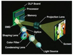
How the Mitsubishi DMD DLP chip works

How the Mitsubishi DMD DLP chip works

Samsung HLT5656WX/XAA TV white dots solution

White dots on your Samsung HLT5656WX/XAA TV screen  can be eliminated by replacing the 4719-001997 DLP chip. Follow the step by step guide below to replace this chip.

Note: These instructions can also be used for the following Samsung models:  

50A650C1FXZA, HLT5055WX/XAA , HLT5076SX/XAA, HLT5087SX/XAA, HLS5087WX/XAA, HL56A650C1FXZA, HLT5656WX/XAA, HLT5676SX/XAA, HLT5687SX/XAA, HLT5687SAX/XAA, HLT5689SX/XAA, HLT6156WX/XAA, HL61A650C1FXZA, HL61A750A1FXZA, HLT6156WX/XAA, HLT6176SX/XAA, HLT6187SAX/XAA, HLT6187SX/XAA, HLS6187WX/XAA, HLT6189SX/XAA, HL67A750A1FXZA, HLT6756WX/XAA, HL72A650C1FXZA, HLT7288WX/XAA

Find this New Mitsubishi/Toshiba 4719-001997 DLP Chip 1910-6143W on Amazon.

Equipment needed

    • Electric Philips screwdriver
    • needle nose pliers or a 5mm nut driver
    • antistatic gloves OR plastic gloves used with an antistatic wrist band
    • soft cloth or brush

Replacing the 4719-001997 DLP Chip in the HLT5656WX/XAA

4719-001997 DLP Chip, Samsung HLT5656WX/XAA RPTV

Step 1

Step 1: Put on the plastic gloves. Loosen all the screws found on the back panel of the Samsung HLT5656WX/XAA. Put the screws to one side and remove the back panel.

4719-001997 DLP Chip, Samsung HLT5656WX/XAA RPTV

Step 2

Step 2: Loosen the two screws holding the lamp bracket in place.

4719-001997 DLP Chip, Samsung HLT5656WX/XAA RPTV

Step 3

Step 3: Remove the 4 screws holding the lamp engine in place. Disconnect all the connectors. Important: don’t yank any cables.

4719-001997 DLP Chip, Samsung HLT5656WX/XAA RPTV

Step 4

Step 4: Carefully remove light engine from the cabinet.

4719-001997 DLP Chip, Samsung HLT5656WX/XAA RPTV

Step 5

Step 5: Remove the 2 screws holding the color wheel protective cover in it place. Avoid touching any of the optical components as this can affect the quality of your picture.

4719-001997 DLP Chip, Samsung HLT5656WX/XAA RPTV

Step 6

Step 6: Carefully disconnect the cables between the terminal board and lamp.

4719-001997 DLP Chip, Samsung HLT5656WX/XAA RPTV

Step 7

Step 7: Disconnect the clip connecting the cooling unit.

4719-001997 DLP Chip, Samsung HLT5656WX/XAA RPTV

Step 8

Step 8: Remove the cooling unit and terminal board.

4719-001997 DLP Chip, Samsung HLT5656WX/XAA RPTV

Step 9

Step 9: Remove the terminal board.

4719-001997 DLP Chip, Samsung HLT5656WX/XAA RPTV

Step 10

Step 10: Loosen the 7 screws holding the terminal cover in place. (Good time to dust this section).

4719-001997 DLP Chip, Samsung HLT5656WX/XAA RPTV

Step 11

Step 11: Carefully pop the terminal out of its holder.

4719-001997 DLP Chip, Samsung HLT5656WX/XAA RPTV

Step 12

Step 12: Unlock the old DLP Chip from the terminal. You may need to use a flat edged screwdriver to pop it out.

4719-001997 DLP Chip, Samsung HLT5656WX/XAA RPTV

Step 13

Step 13: Place the new DLP chip into place. Handle the DLP CHIP only by the edges because it is very sensitive to static electricity.

4719-001997 DLP Chip, Samsung HLT5656WX/XAA RPTV

Step 14

Step 14: Put the terminal back into its holder.

4719-001997 DLP Chip, Samsung HLT5656WX/XAA RPTV

Step 15

Step 15: Tighten the 7 screws holding the terminal in place.


4719-001997 DLP Chip, Samsung HLT5656WX/XAA RPTV

Step 16

Step 16: Replace the terminal board’s cover.

4719-001997 DLP Chip, Samsung HLT5656WX/XAA RPTV

Step 17

Step 17: Reconnect the clip holding the cooling unit.

4719-001997 DLP Chip, Samsung HLT5656WX/XAA RPTV

Step 18

Step 18: Re-connect the cables between the terminal board and lamp.

4719-001997 DLP Chip, Samsung HLT5656WX/XAA RPTV

Step 19

Step 19: Tighten the 2 screws holding the color wheel protective cover in it place. Avoid touching any of the optical components as this can affect the quality of your picture.

4719-001997 DLP Chip, Samsung HLT5656WX/XAA RPTV

Step 20

Step 20: Carefully replace the light engine back into the cabinet.

4719-001997 DLP Chip, Samsung HLT5656WX/XAA RPTV

Step 21

Step 21: Replace and tighten the 4 screws holding the lamp engine in place. Re-connect all the connectors.

4719-001997 DLP Chip, Samsung HLT5656WX/XAA RPTV

Step 22

Step 22: Put the light engine back into the RPTV. Tighten both screws that keep the back bracket in place.

.

4719-001997 DLP Chip, Samsung HLT6756WX RPTV

Step 23

Step 23: Put the back panel back onto the TV. Put the screws back into place and tighten them. Enjoy the crisp, clear picture on your Samsung HLT6756WX RPTV.

Learn more about your Samsung HLT5656WX/XAA RPTV:

Tagged with: , , ,

no white death Samsung HLS6187WX/XAA TV

Solving white dots problem on Samsung HLS6187WX/XAA TV

The white dot problem on your Samsung HLS6187WX/XAA  TV screen  can be eliminated by replacing the 4719-001997 DLP chip. Follow the step by step guide below to replace this chip.

Note: These instructions can also be used for the following Samsung models: 

50A650C1FXZA, HLT5055WX/XAA , HLT5076SX/XAA, HLT5087SX/XAA, HLS5087WX/XAA, HL56A650C1FXZA, HLT5656WX/XAA, HLT5676SX/XAA, HLT5687SX/XAA, HLT5687SAX/XAA, HLT5689SX/XAA, HLT6156WX/XAA, HL61A650C1FXZA, HL61A750A1FXZA, HLT6156WX/XAA, HLT6176SX/XAA, HLT6187SAX/XAA, HLT6187SX/XAA, HLS6187WX/XAA, HLT6189SX/XAA, HL67A750A1FXZA, HLT6756WX/XAA, HL72A650C1FXZA, HLT7288WX/XAA

Find this New Mitsubishi/Toshiba 4719-001997 DLP Chip 1910-6143W on Amazon.

Equipment needed

    • Electric Philips screwdriver
    • needle nose pliers or a 5mm nut driver
    • antistatic gloves OR plastic gloves used with an antistatic wrist band
    • soft cloth or brush

Replacing the 4719-001997 DLP Chip in the HLS6187WX/XAA

4719-001997 DLP Chip, Samsung HLS6187WX/XAA RPTV

Step 1

Step 1: Put on the plastic gloves. Loosen all the screws found on the back panel of the Samsung HLS6187WX/XAA.  Put the screws to one side and remove the back panel.

4719-001997 DLP Chip, Samsung HLS6187WX/XAA RPTV

Step 2

Step 2: Loosen the two screws holding the lamp bracket in place.

4719-001997 DLP Chip, Samsung HLS6187WX/XAA RPTV

Step 3

Step 3: Remove the 4 screws holding the lamp engine in place. Disconnect all the connectors. Important: don’t yank any cables.

4719-001997 DLP Chip, Samsung HLS6187WX/XAA RPTV

Step 4

Step 4: Carefully remove light engine from the cabinet.

4719-001997 DLP Chip, Samsung HLS6187WX/XAA RPTV

Step 5

Step 5: Remove the 2 screws holding the color wheel protective cover in it place. Avoid touching any of the optical components as this can affect the quality of your picture.

4719-001997 DLP Chip, Samsung HLS6187WX/XAA RPTV

Step 6

Step 6: Carefully disconnect the cables between the terminal board and lamp.

4719-001997 DLP Chip, Samsung HLS6187WX/XAA RPTV

Step 7

Step 7: Disconnect the clip connecting the cooling unit.

4719-001997 DLP Chip, Samsung HLS6187WX/XAA RPTV

Step 8

Step 8: Remove the cooling unit and terminal board.

4719-001997 DLP Chip, Samsung HLS6187WX/XAA RPTV

Step 9

Step 9: Remove the terminal board.

4719-001997 DLP Chip, Samsung HLS6187WX/XAA RPTV

Step 10

Step 10: Loosen the 7 screws holding the terminal cover in place. (Good time to dust this section).

4719-001997 DLP Chip, Samsung HLS6187WX/XAA RPTV

Step 11

Step 11: Carefully pop the terminal out of its holder.

4719-001997 DLP Chip, Samsung HLS6187WX/XAA RPTV

Step 12

Step 12: Unlock the old DLP Chip from the terminal. You may need to use a flat edged screwdriver to pop it out.

4719-001997 DLP Chip, Samsung HLS6187WX/XAA RPTV

Step 13

Step 13: Place the new DLP chip into place. Handle the DLP CHIP only by the edges because it is very sensitive to static electricity.

4719-001997 DLP Chip, Samsung HLS6187WX/XAA RPTV

Step 14

Step 14: Put the terminal back into its holder.

4719-001997 DLP Chip, Samsung HLS6187WX/XAA RPTV

Step 15

Step 15: Tighten the 7 screws holding the terminal in place.


4719-001997 DLP Chip, Samsung HLS6187WX/XAA RPTV

Step 16

Step 16: Replace the terminal board’s cover.

4719-001997 DLP Chip, Samsung HLS6187WX/XAA RPTV

Step 17

Step 17: Reconnect the clip holding the cooling unit.

4719-001997 DLP Chip, Samsung HLS6187WX/XAA RPTV

Step 18

Step 18: Re-connect the cables between the terminal board and lamp.

4719-001997 DLP Chip, Samsung HLS6187WX/XAA RPTV

Step 19

Step 19: Tighten the 2 screws holding the color wheel protective cover in it place. Avoid touching any of the optical components as this can affect the quality of your picture.

4719-001997 DLP Chip, Samsung HLS6187WX/XAA RPTV

Step 20

Step 20: Carefully replace the light engine back into the cabinet.

4719-001997 DLP Chip, Samsung HLS6187WX/XAA RPTV

Step 21

Step 21: Replace and tighten the 4 screws holding the lamp engine in place. Re-connect all the connectors.

4719-001997 DLP Chip, Samsung HLS6187WX/XAA RPTV

Step 22

Step 22: Put the light engine back into the RPTV. Tighten both screws that keep the back bracket in place.

4719-001997 DLP Chip, Samsung HLS6187WX/XAA RPTV

Step 23

Step 23: Put the back panel back onto the TV. Put the screws back into place and tighten.  Enjoy the crisp, clear picture on your Samsung HLS6187WX/XAA RPTV.

Learn more about your Samsung HLS6187WX/XAA RPTV:

Tagged with: , , ,

Get rid of white dots on the Samsung HLS5087WX/XAA screen

White dots on your Samsung HLS5087WX/XAA screen  can be eliminated by replacing the 4719-001997 DLP chip. Follow the step by step guide below to replace this chip.

Note: These instructions can also be used for the following Samsung models:  


50A650C1FXZA, HLT5055WX/XAA , HLT5076SX/XAA, HLT5087SX/XAA, HLS5087WX/XAA, HL56A650C1FXZA, HLT5656WX/XAA, HLT5676SX/XAA, HLT5687SX/XAA, HLT5687SAX/XAA, HLT5689SX/XAA, HLT6156WX/XAA, HL61A650C1FXZA, HL61A750A1FXZA, HLT6156WX/XAA, HLT6176SX/XAA, HLT6187SAX/XAA, HLT6187SX/XAA, HLS6187WX/XAA, HLT6189SX/XAA, HL67A750A1FXZA, HLT6756WX/XAA, HL72A650C1FXZA, HLT7288WX/XAA

Find this New Mitsubishi/Toshiba 4719-001997 DLP Chip 1910-6143W on Amazon.

Equipment needed

    • Electric Philips screwdriver
    • needle nose pliers or a 5mm nut driver
    • antistatic gloves OR plastic gloves used with an antistatic wrist band
    • soft cloth or brush

Replacing the 4719-001997 DLP Chip in the HLS5087WX/XAA

4719-001997 DLP Chip, Samsung HLS5087WX/XAA RPTV

Step 1

Step 1: Put on the plastic gloves. Loosen all the screws found on the back panel of the Samsung HLS5087WX/XAA. Put the screws to one side and remove the back panel.

4719-001997 DLP Chip, Samsung HLS5087WX/XAA RPTV

Step 2

Step 2: Loosen the two screws holding the lamp bracket in place.

4719-001997 DLP Chip, Samsung HLS5087WX/XAA RPTV

Step 3

Step 3: Remove the 4 screws holding the lamp engine in place. Disconnect all the connectors. Important: don’t yank any cables.

4719-001997 DLP Chip, Samsung HLS5087WX/XAA RPTV

Step 4

Step 4: Carefully remove light engine from the cabinet.

4719-001997 DLP Chip, Samsung HLS5087WX/XAA RPTV

Step 5

Step 5: Remove the 2 screws holding the color wheel protective cover in it place. Avoid touching any of the optical components as this can affect the quality of your picture.

4719-001997 DLP Chip, Samsung HLS5087WX/XAA RPTV

Step 6

Step 6: Carefully disconnect the cables between the terminal board and lamp.

4719-001997 DLP Chip, Samsung HLS5087WX/XAA RPTV

Step 7

Step 7: Disconnect the clip connecting the cooling unit.

4719-001997 DLP Chip, Samsung HLS5087WX/XAA RPTV

Step 8

Step 8: Remove the cooling unit and terminal board.

4719-001997 DLP Chip, Samsung HLS5087WX/XAA RPTV

Step 9

Step 9: Remove the terminal board.

4719-001997 DLP Chip, Samsung HLS5087WX/XAA RPTV

Step 10

Step 10: Loosen the 7 screws holding the terminal cover in place. (Good time to dust this section).

4719-001997 DLP Chip, Samsung HLS5087WX/XAA RPTV

Step 11

Step 11: Carefully pop the terminal out of its holder.

4719-001997 DLP Chip, Samsung HLS5087WX/XAA RPTV

Step 12

Step 12: Unlock the old DLP Chip from the terminal. You may need to use a flat edged screwdriver to pop it out.

4719-001997 DLP Chip, Samsung HLS5087WX/XAA RPTV

Step 13

Step 13: Place the new DLP chip into place. Handle the DLP CHIP only by the edges because it is very sensitive to static electricity.

4719-001997 DLP Chip, Samsung HLS5087WX/XAA RPTV

Step 14

Step 14: Put the terminal back into its holder.

4719-001997 DLP Chip, Samsung HLS5087WX/XAA RPTV

Step 15

Step 15: Tighten the 7 screws holding the terminal in place.


4719-001997 DLP Chip, Samsung HLS5087WX/XAA RPTV

Step 16

Step 16: Replace the terminal board’s cover.

4719-001997 DLP Chip, Samsung HLS5087WX/XAA RPTV

Step 17

Step 17: Reconnect the clip holding the cooling unit.

4719-001997 DLP Chip, Samsung HLS5087WX/XAA RPTV

Step 18

Step 18: Re-connect the cables between the terminal board and lamp.

4719-001997 DLP Chip, Samsung HLS5087WX/XAA RPTV

Step 19

Step 19: Tighten the 2 screws holding the color wheel protective cover in it place. Avoid touching any of the optical components as this can affect the quality of your picture.

4719-001997 DLP Chip, Samsung HLS5087WX/XAA RPTV

Step 20

Step 20: Carefully replace the light engine back into the cabinet.

4719-001997 DLP Chip, Samsung HLS5087WX/XAA RPTV

Step 21

Step 21: Replace and tighten the 4 screws holding the lamp engine in place. Re-connect all the connectors.

4719-001997 DLP Chip, Samsung HLS5087WX/XAA RPTV

Step 22

Step 22: Put the light engine back into the RPTV. Tighten both screws that keep the back bracket in place.

4719-001997 DLP Chip, Samsung HLS5087WX/XAA RPTV

Step 23

Step 23: Put the back panel on the TV. Put the screws back into place and tighten them.  Enjoy the crisp, clear picture on your Samsung HLS5087WX/XAA RPTV.

Learn more about your Samsung HLS5087WX/XAA RPTV:

Tagged with: , ,

Get rid of white dots on the Samsung HLT5055WX/XAA screen
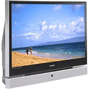
White dots on your Samsung HLT5055WX/XAA screen  can be eliminated by replacing the 4719-001997 DLP chip. Follow the step by step guide below.

Note: These instructions can also be used for the following Samsung models:  

50A650C1FXZA, HLT5055WX/XAA , HLT5076SX/XAA, HLT5087SX/XAA, HLS5087WX/XAA, HL56A650C1FXZA, HLT5656WX/XAA, HLT5676SX/XAA, HLT5687SX/XAA, HLT5687SAX/XAA, HLT5689SX/XAA, HLT6156WX/XAA, HL61A650C1FXZA, HL61A750A1FXZA, HLT6156WX/XAA, HLT6176SX/XAA, HLT6187SAX/XAA, HLT6187SX/XAA, HLS6187WX/XAA, HLT6189SX/XAA, HL67A750A1FXZA, HLT6756WX/XAA, HL72A650C1FXZA, HLT7288WX/XAA

Find this New Mitsubishi/Toshiba 4719-001997 DLP Chip 1910-6143W on Amazon.

Equipment needed

    • Electric Philips screwdriver
    • needle nose pliers or a 5mm nut driver
    • antistatic gloves OR plastic gloves used with an antistatic wrist band
    • soft cloth or brush

Replacing the 4719-001997 DLP Chip

4719-001997 DLP Chip, Samsung HLT5055WX/XAA RPTV

Step 1

Step 1: Put on the plastic gloves. Loosen all the screws found on the back panel of the Samsung HLT5055WX/XAA. Put the screws to one side and remove the back panel.

4719-001997 DLP Chip, Samsung HLT5055WX/XAA RPTV

Step 2

Step 2: Loosen the two screws holding the lamp bracket in place.

4719-001997 DLP Chip, Samsung HLT5055WX/XAA RPTV

Step 3

Step 3: Remove the 4 screws holding the lamp engine in place. Disconnect all the connectors. Important: don’t yank any cables.

4719-001997 DLP Chip, Samsung HLT5055WX/XAA RPTV

Step 4

Step 4: Carefully remove light engine from the cabinet.

4719-001997 DLP Chip, Samsung HLT5055WX/XAA RPTV

Step 5

Step 5: Remove the 2 screws holding the color wheel protective cover in it place. Avoid touching any of the optical components as this can affect the quality of your picture.

4719-001997 DLP Chip, Samsung HLT5055WX/XAA RPTV

Step 6

Step 6: Carefully disconnect the cables between the terminal board and lamp.

4719-001997 DLP Chip, Samsung HLT5055WX/XAA RPTV

Step 7

Step 7: Disconnect the clip connecting the cooling unit.

4719-001997 DLP Chip, Samsung HLT5055WX/XAA RPTV

Step 8

Step 8: Remove the cooling unit and terminal board.

4719-001997 DLP Chip, Samsung HLT5055WX/XAA RPTV

Step 9

Step 9: Remove the terminal board.

4719-001997 DLP Chip, Samsung HLT5055WX/XAA RPTV

Step 10

Step 10: Loosen the 7 screws holding the terminal cover in place. (Good time to dust this section).

4719-001997 DLP Chip, Samsung HLT5055WX/XAA RPTV

Step 11

Step 11: Carefully pop the terminal out of its holder.

4719-001997 DLP Chip, Samsung HLT5055WX/XAA RPTV

Step 12

Step 12: Unlock the old DLP Chip from the terminal. You may need to use a flat edged screwdriver to pop it out.

4719-001997 DLP Chip, Samsung HLT5055WX/XAA RPTV

Step 13

Step 13: Place the new DLP chip into place. Handle the DLP CHIP only by the edges because it is very sensitive to static electricity.

4719-001997 DLP Chip, Samsung HLT5055WX/XAA RPTV

Step 14

Step 14: Put the terminal back into its holder.

4719-001997 DLP Chip, Samsung HLT5055WX/XAA RPTV

Step 15

Step 15: Tighten the 7 screws holding the terminal in place.


4719-001997 DLP Chip, Samsung HLT5055WX/XAA RPTV

Step 16

Step 16: Replace the terminal board’s cover.

4719-001997 DLP Chip, Samsung HLT5055WX/XAA RPTV

Step 17

Step 17: Reconnect the clip holding the cooling unit.

4719-001997 DLP Chip, Samsung HLT5055WX/XAA RPTV

Step 18

Step 18: Re-connect the cables between the terminal board and lamp.

4719-001997 DLP Chip, Samsung HLT5055WX/XAA RPTV

Step 19

Step 19: Tighten the 2 screws holding the color wheel protective cover in it place. Avoid touching any of the optical components as this can affect the quality of your picture.

4719-001997 DLP Chip, Samsung HLT5055WX/XAA RPTV

Step 20

Step 20: Carefully replace the light engine back into the cabinet.

4719-001997 DLP Chip, Samsung HLT5055WX/XAA RPTV

Step 21

Step 21: Replace and tighten the 4 screws holding the lamp engine in place. Re-connect all the connectors.

4719-001997 DLP Chip, Samsung HLT5055WX/XAA RPTV

Step 22

Step 22: Put the light engine back into the RPTV. Tighten both screws that keep the back bracket in place.

4719-001997 DLP Chip, Samsung HLT5055WX/XAA RPTV

Step 23

Step 23: Put the back panel back onto the TV. Put the screws back into place and tighten them. Enjoy the crisp, clear picture on your Samsung HLT5055WX/XAA RPTV.

Learn more about your Samsung HLT5055WX/XAA RPTV:

Tagged with: , ,

Samsun 50A650C1FXZA_TVWhite dots on the Samsumg 50A650C1FXZA means the DLP chip needs replacing
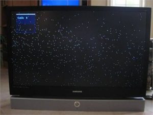
Replace your Samsung 50A650C1FXZA DLP chip for under $300 and get rid of those white dots.

Note: These instructions can also be used for the following Samsung models:  

H50A650C1FXZA, HLT5055WX/XAA , HLT5076SX/XAA, HLT5087SX/XAA, HLS5087WX/XAA, HL56A650C1FXZA, HLT5656WX/XAA, HLT5676SX/XAA, HLT5687SX/XAA, HLT5687SAX/XAA, HLT5689SX/XAA, HLT6156WX/XAA, HL61A650C1FXZA, HL61A750A1FXZA, HLT6156WX/XAA, HLT6176SX/XAA, HLT6187SAX/XAA, HLT6187SX/XAA, HLS6187WX/XAA, HLT6189SX/XAA, HL67A750A1FXZA, HLT6756WX/XAA, HL72A650C1FXZA, HLT7288WX/XAA

Find this New Mitsubishi/Toshiba 4719-001997 DLP Chip 1910-6143W on Amazon.

Equipment needed

    • Electric Philips screwdriver
    • needle nose pliers or a 5mm nut driver
    • antistatic gloves OR plastic gloves used with an antistatic wrist band
    • soft cloth or brush

Replacing the 4719-001997 50A650C1FXZA DLP Chip

4719-001997 DLP Chip, Samsung 50A650C1FXZA RPTV

Step 1

Step 1: Put on the plastic gloves. Loosen all the screws found on the back panel. Put the screws to one side and remove the back panel.

4719-001997 DLP Chip, Samsung 50A650C1FXZA RPTV

Step 2

Step 2: Loosen the two screws holding the lamp bracket in place.

4719-001997 DLP Chip, Samsung 50A650C1FXZA RPTV

Step 3

Step 3: Remove the 4 screws holding the lamp engine in place. Disconnect all the connectors. Important: don’t yank any cables.

4719-001997 DLP Chip, Samsung 50A650C1FXZA RPTV

Step 4

Step 4: Carefully remove light engine from the cabinet.

4719-001997 DLP Chip, Samsung 50A650C1FXZA RPTV

Step 5

Step 5: Remove the 2 screws holding the color wheel protective cover in it place. Avoid touching any of the optical components as this can affect the quality of your picture.

4719-001997 DLP Chip, Samsung 50A650C1FXZA RPTV

Step 6

Step 6: Carefully disconnect the cables between the terminal board and lamp.

4719-001997 DLP Chip, Samsung 50A650C1FXZA RPTV

Step 7

Step 7: Disconnect the clip connecting the cooling unit.

4719-001997 DLP Chip, Samsung 50A650C1FXZA RPTV

Step 8

Step 8: Remove the cooling unit and terminal board.

4719-001997 DLP Chip, Samsung 50A650C1FXZA RPTV

Step 9

Step 9: Remove the terminal board.

4719-001997 DLP Chip, Samsung 50A650C1FXZA RPTV

Step 10

Step 10: Loosen the 7 screws holding the terminal cover in place. (Good time to dust this section).

4719-001997 DLP Chip, Samsung 50A650C1FXZA RPTV

Step 11

Step 11: Carefully pop the terminal out of its holder.

4719-001997 DLP Chip, Samsung 50A650C1FXZA RPTV

Step 12

Step 12: Unlock the old DLP Chip from the terminal. You may need to use a flat edged screwdriver to pop it out.

4719-001997 DLP Chip, Samsung 50A650C1FXZA RPTV

Step 13

Step 13: Place the new DLP chip into place. Handle the DMD DLP CHIP only by the edges because it is very sensitive to static electricity.

4719-001997 DLP Chip, Samsung 50A650C1FXZA RPTV

Step 14

Step 14: Put the terminal back into its holder.

4719-001997 DLP Chip, Samsung 50A650C1FXZA RPTV

Step 15

Step 15: Tighten the 7 screws holding the terminal in place.


4719-001997 DLP Chip, Samsung 50A650C1FXZA RPTV

Step 16

Step 16: Replace the terminal board’s cover.

4719-001997 DLP Chip, Samsung 50A650C1FXZA RPTV

Step 17

Step 17: Reconnect the clip holding the cooling unit.

4719-001997 DLP Chip, Samsung 50A650C1FXZA RPTV

Step 18

Step 18: Re-connect the cables between the terminal board and lamp.

4719-001997 DLP Chip, Samsung 50A650C1FXZA RPTV

Step 19

Step 19: Tighten the 2 screws holding the color wheel protective cover in it place. Avoid touching any of the optical components as this can affect the quality of your picture.

4719-001997 DLP Chip, Samsung 50A650C1FXZA RPTV

Step 20

Step 20: Carefully replace the light engine back into the cabinet.

4719-001997 DLP Chip, Samsung 50A650C1FXZA RPTV

Step 21

Step 21: Replace and tighten the 4 screws holding the lamp engine in place. Re-connect all the connectors.

4719-001997 DLP Chip, Samsung 50A650C1FXZA RPTV

Step 22

Step 22: Put the light engine back into the RPTV. Tighten both screws that keep the back bracket in place.

4719-001997 DLP Chip, Samsung 50A650C1FXZA RPTV

Step 23

Step 23: Put the back panel back onto the TV. Put the screws back into place and tighten them. Enjoy the crisp, clear picture on your Samsung 50A650C1FXZA RPTV.

Learn more about your Samsung 50A650C1FXZA RPTV:

Tagged with: , ,

White dots on Samsung HL72A650C1FXZA screen can easily be repaired
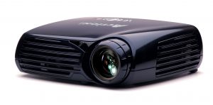
Samsung HL72A650C1FXZA white dots are a sign that your DLP chip has broken and needs to be replaced.

Note: These instructions can also be used for the following Samsung models: 

50A650C1FXZA, HLT5055WX/XAA , HLT5076SX/XAA, HLT5087SX/XAA, HLS5087WX/XAA, HL56A650C1FXZA, HLT5656WX/XAA, HLT5676SX/XAA, HLT5687SX/XAA, HLT5687SAX/XAA, HLT5689SX/XAA, HLT6156WX/XAA, HL61A650C1FXZA, HL61A750A1FXZA, HLT6156WX/XAA, HLT6176SX/XAA, HLT6187SAX/XAA, HLT6187SX/XAA, HLS6187WX/XAA, HLT6189SX/XAA, HL67A750A1FXZA, HLT6756WX/XAA, HL72A650C1FXZA, HLT7288WX/XAA

Find this New Mitsubishi/Toshiba 4719-001997 DLP Chip 1910-6143W on Amazon.

Equipment needed

    • Electric Philips screwdriver
    • needle nose pliers or a 5mm nut driver
    • antistatic gloves OR plastic gloves used with an antistatic wrist band
    • soft cloth or brush

Replacing the 4719-001997 DLP Chip

4719-001997 DLP Chip, Samsung HL72A650C1FXZA

Step 1

Step 1: Put on the plastic gloves. Loosen all the screws found on the back panel. Put the screws to one side and remove the back panel.

4719-001997 DLP Chip, Samsung HL72A650C1FXZA

Step 2

Step 2: Loosen the two screws holding the lamp bracket in place.

4719-001997 DLP Chip, Samsung HL72A650C1FXZA

Step 3

Step 3: Remove the 4 screws holding the lamp engine in place. Disconnect all the connectors. Important: don’t yank any cables.

4719-001997 DLP Chip, Samsung HL72A650C1FXZA

Step 4

Step 4: Carefully remove light engine from the cabinet.

4719-001997 DLP Chip, Samsung HHL72A650C1FXZA RPTV

Step 5

Step 5: Remove the 2 screws holding the color wheel protective cover in it place. Avoid touching any of the optical components as this can affect the quality of your picture.

4719-001997 DLP Chip, Samsung HL72A650C1FXZA RPTV

Step 6

Step 6: Carefully disconnect the cables between the terminal board and lamp.

4719-001997 DLP Chip, Samsung HL72A650C1FXZA RPTV

Step 7

Step 7: Disconnect the clip connecting the cooling unit.

4719-001997 DLP Chip, Samsung HL72A650C1FXZA RPTV

Step 8

Step 8: Remove the cooling unit and terminal board.

4719-001997 DLP Chip, Samsung HL72A650C1FXZA RPTV

Step 9

Step 9: Remove the terminal board.

4719-001997 DLP Chip, Samsung HL72A650C1FXZA RPTV

Step 10

Step 10: Loosen the 7 screws holding the terminal cover in place. (Good time to dust this section).

4719-001997 DLP Chip, Samsung HL72A650C1FXZA RPTV

Step 11

Step 11: Carefully pop the terminal out of its holder.

4719-001997 DLP Chip, Samsung HL72A650C1FXZA RPTV

Step 12

Step 12: Unlock the old DLP Chip from the terminal. You may need to use a flat edged screwdriver to pop it out.

4719-001997 DLP Chip, Samsung HL72A650C1FXZA RPTV

Step 13

Step 13: Place the new DLP chip into place. Handle the DMD DLP CHIP only by the edges because it is very sensitive to static electricity.

4719-001997 DLP Chip, Samsung HL72A650C1FXZA RPTV

Step 14

Step 14: Put the terminal back into its holder.

4719-001997 DLP Chip, Samsung HL72A650C1FXZA RPTV

Step 15

Step 15: Tighten the 7 screws holding the terminal in place.


4719-001997 DLP Chip, Samsung HL72A650C1FXZA RPTV

Step 16

Step 16: Replace the terminal board’s cover.

4719-001997 DLP Chip, Samsung HL72A650C1FXZA RPTV

Step 17

Step 17: Reconnect the clip holding the cooling unit.

4719-001997 DLP Chip, Samsung HL72A650C1FXZA RPTV

Step 18

Step 18: Re-connect the cables between the terminal board and lamp.

4719-001997 DLP Chip, Samsung HL72A650C1FXZA RPTV

Step 19

Step 19: Tighten the 2 screws holding the color wheel protective cover in it place. Avoid touching any of the optical components as this can affect the quality of your picture.

4719-001997 DLP Chip, Samsung HL72A650C1FXZA RPTV

Step 20

Step 20: Carefully replace the light engine back into the cabinet.

4719-001997 DLP Chip, Samsung HL72A650C1FXZA RPTV

Step 21

Step 21: Replace and tighten the 4 screws holding the lamp engine in place. Re-connect all the connectors.

4719-001997 DLP Chip, Samsung HL72A650C1FXZA RPTV

Step 22

Step 22: Put the light engine back into the RPTV. Tighten both screws that keep the back bracket in place.

4719-001997 DLP Chip, Samsung HL72A650C1FXZA RPTV

Step 23

Step 23: Put the back panel onto the TV. Put the screws back into place and tighten them. Enjoy the crisp, clear picture on your Samsung HL72A650C1FXZA RPTV.

Learn more about your Samsung HL72A650C1FXZA RPTV:

Tagged with: , ,

ProjectionDesign Action! Model One projectorReplacement ProjectionDesign Action Model One projector lamp

Your ProjectionDesign Action Model One projector uses the ProjectionDesign 400-0003-00 Projector Lamp. Be sure to buy your ProjectionDesign Action Model 1 projector lamp from an authorized dealer to keep your projector working properly.

Find this replacement lamp on Amazon from the following authorized dealers:


6 reasons to avoid counterfeit lamps:

End of life warning signs

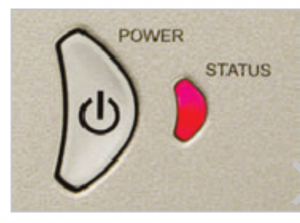
Projection_Design_Action_Mode_One_l400-0003-00 Projector Lamp_warningWhen it’s time to replace the ProjectionDesign Action Model 1 projector lamp the projector lamp status indicators will turn red. Other warning signs may include a darker screen or colors that appear washed out or an deteriorating screen image.
How to replace

Before installation follow these important safety steps:

  • Turn off the ProjectionDesign Action Model 1 projector:
  • Unplug the AC cord.
  • These projectors operate under high temperatures and there is a risk of burning if the projector has not cooled enough. Allow the ProjectionDesign Action Model One to cool for one hour. It should be cool to the touch.

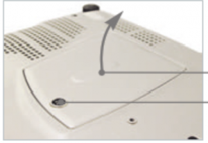
Projection_Design_Action_Mode_One_l400-0003-00 Projector Lamp_cover

Projection_Design_Action_Mode_One_l400-0003-00 Projector Lamp_loosen_screws

Remove the two screws from the ProjectionDesign Action Model 1 projector lamp cover. Remove the projector lamp cover.

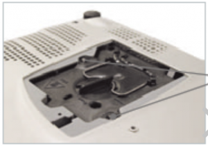
Loosen the two screws holding the ProjectionDesign 400-0003-00 projector lamp in place.


Projection_Design_Action_Mode_One_l400-0003-
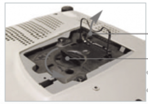
Turn the lamp knob counter clockwise to the unlocked position.

NOTE: The ProjectionDesign 400-0003-00 projector lamp contains mercury and should not be thrown into regular garbage. Recycle this lamp!


Projection_Design_Action_Mode_One_l400-0003-00 Projector Lamp_insert

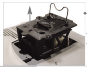
Pull out the ProjectionDesign 400-0003-00 projector lamp.
Tighten the screws on the projector lamp lid.

Projection_Design_Action_Mode_One_l400-0003-00 Projector Lamp_replacement
Place the new ProjectionDesign 400-0003-00 projector lamp into the projector. Take care not to touch the actual bulb. Oil from your fingerprints will create black spots onto the bulb.
Projection_Design_Action_Mode_One_l400-0003-00 Projector Lamp_tighten
Tighten the screws on the projector lamp. Turn the lamp knob
clockwise to the locked position.
Put the lamp cover back on and tighten the two screws holding the cover in place.


Resetting the projector lamp timer

Each time you replace the ProjectionDesign 400-0003-00 projector lamp you will need to reset the ProjectionDesign Action Model 1 lamp timer so the projector can accurately track the lamp hours. To reset the:
  • Open the MENU option. Press ENTER.
  • Scroll down to the UTILTIES submenu.
  • Press reset the lamp time.

Extending the projector lamp life

  • Use the Eco Mode for more lamp hours.
  • Keep your air filters clean to avoid overheating the projector.
  • Make sure there is enough airflow around the ProjectionDesign Action Model 1.
  • Learn more with Top tips for extending DLP projector lamp life

Learn more tips for extending lamp life.

Tagged with: , , , ,
Join the discussion on Facebook! All your questions, answered! The Screen & Projector Group